Executive summary
As logic and memory manufacturers push into the 2-nm era, nitrogen moves from a “utility” to a process enabler. Ultra-high-purity (UHP) N₂ safeguards dielectrics, photoresists, and advanced metallization while stabilizing tool environments. This article outlines how an industrial nitrogen generator should be engineered for 2-nm-class fabs: purity targets and contaminants, header pressure strategy, redundancy, analytics, energy use (kWh/Nm³), and a commissioning/quality plan. Two text tables are included for quick specification and cost modeling.

1) Purity and contaminants that matter at 2-nm
At advanced nodes, the question is no longer “99.999% vs. 99.9%” but which trace species must be pushed into the sub-ppm—often ppb—domain. Oxygen and moisture remain the big two, but total hydrocarbons (THC), carbon monoxide/dioxide, and particles/metallics can also compromise yields and surface chemistry.
Typical UHP N₂ distribution targets for advanced fabs (indicative ranges; tool vendor specs prevail):
- O₂: ≤ 1 ppm (critical tools may call for ≤ 100 ppb)
- H₂O (dew point): ≤ −70 °C (≈ 3 ppmv) down to ≤ −90 °C for ultra-dry uses
- THC (as CH₄ equiv.): ≤ 100 ppb–1 ppm
- CO / CO₂: ≤ 1 ppm each (stricter at some tools)
- Particles: ≥ 0.003 µm control in point-of-use filtration; 0.003–0.01 µm capture upstream
- Metals/ions: non-detectable within analytical method limits for UHP gas systems
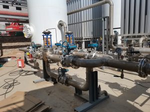
Meeting those levels reliably requires both generation and polishing plus an immaculate distribution system (316L EP tubing, orbital welds, UHP valves, minimal dead-legs, helium leak-tested lines).
-769x1024.png)
2) Supply architectures that scale and survive
A 2-nm-ready industrial nitrogen generator can be built around one of three patterns:
- Cryogenic ASU on site (central UHP):
- Strengths: intrinsic high purity, large base loads (≥ 5 000 Nm³/h), favorable OPEX at scale, LIN buffer.
- Consider when fab has campus-level demand or multiple lines coming online.
- PSA-based trains + polishing (catalytic de-oxo + dryer + UHP filtration):
- Strengths: modularity, fast expansion, excellent turndown (30–100%).
- For 2-nm, pair with de-oxo reactor (H₂ addition) and twin-tower dryers to push O₂/H₂O to spec.
- Use N+1 or 2N trains to protect uptime.
- Membrane (select non-critical loads):
- Strengths: simplicity, low maintenance.
- Typically limited to ~95–99.5% purity—best for tool exhaust purges, fire-suppression interfaces, or utility spaces, not critical process purges.
In practice, many fabs deploy a hybrid: cryogenic or high-spec PSA for process headers, smaller PSA/membrane blocks for utilities, and a liquid nitrogen backup (LIN) for black-swan events and planned outages.
3) Distribution pressure, flow stability, and transients
- Header pressure: 6–8 bar(g) for main process N₂ is common; local boosters feed 10–20 bar(g) tools if required.
- Point-of-use (POU) control: high-resolution regulators and 0.003 µm UHP filters immediately upstream of tools.
- Transient handling: install surge volumes and smart pressure-flow control to absorb step-changes during lot starts, chamber cleans, and abatement events.
- Segmentation: ring-main design with sectional isolation valves; separate “critical” and “non-critical” sub-headers to prevent cross-contamination.
4) Analytics and quality assurance
A 2-nm-class industrial nitrogen generator must be paired with continuous analytics:
- Continuous analyzers: O₂ (ppb–ppm), H₂O (−70 to −90 °C dew point), THC (FID), CO/CO₂ (NDIR), plus periodic metals/ionic audits.
- SPC & alarms: trend baselines per header segment and per train; dual-range sensors mitigate drift; alarm thresholds set below tool trip points.
- Validation: FAT/SAT with purity maps, helium leak-rate acceptance, filter integrity testing, pressure-decay on segments, and documented POU cleanliness.
- Change control: post-maintenance qualification (PMQ) on analyzers, dryers, de-oxo catalysts, and filter elements.
5) Energy and OPEX thinking (kWh/Nm³)
Energy dominates OPEX. Ballpark figures for sizing (indicative; depends on altitude, ambient, and metallurgy):
- PSA base production (99.9%–5N feed to polishing): ~0.35–0.55 kWh/Nm³
- Polishing (de-oxo + dryer + UHP filtration): +0.03–0.10 kWh/Nm³
- Distribution/boosting (per 10 bar gain): +0.10–0.18 kWh/Nm³
- Cryogenic (large-scale ASU): competitive at high flows; site-specific curves
Design levers: oil-free compressors with VFDs, heat-integrated dryers, high-efficiency catalysts, optimized equalization on PSA cycles, and tight leak-rate management on headers.
6) Capacity, modularity, and uptime
For 2-nm, availability is a specification. Engineer for:
- N+1 or 2N trains for the critical header; cross-ties between trains.
- Dual polishing lines with automatic switchover.
- LIN backup with auto-valving and dew-point reconciliation logic on reintroduction.
- Digital twin / predictive maintenance on valves, blowers, compressors, and analyzers.
- Mean time to repair (MTTR) under 2–4 hours for any single subsystem; critical spares on site.
A well-architected industrial nitrogen generator should support ≥ 99.999% supply reliability at the header when paired with proper redundancy and a LIN safety net.
7) Clean construction: materials and methods
- Materials: 316L stainless steel, electropolished, sulfur-controlled heats; UHP-rated diaphragms and seats.
- Joints: orbital GTAW welds with oxygen-free purge; traceable weld logs.
- Cleaning: multi-stage degrease, deionized water rinse, filtered dry N₂ blow-down; cleanliness verification by wipe/gravimetric and particle counters.
- Filtration: staged—coalescing at generation skid, sub-micron in distribution, and 0.003 µm POU filters.
8) Technical Table A — Recommended N₂ specs by use area (text-only)
Table A — 2-nm Fab Nitrogen Specification Guide (Indicative)
Use Area / Example       O2 Limit          Dew Point (°C)      THC (as CH4)     CO/CO2          Particles (POU)         Notes
-----------------------  ----------------  ------------------  ---------------  --------------  -----------------------  --------------------------------------------
Litho/Resist Handling    ≤ 100 ppb–1 ppm   ≤ -80 to -90        ≤ 100–300 ppb    ≤ 0.5–1 ppm     ≥ 0.003 µm retention     Strict organics/moisture control
ALD/CVD/PVD Purges       ≤ 1 ppm           ≤ -80               ≤ 0.5–1 ppm      ≤ 1 ppm         ≥ 0.003 µm retention     Stable flow/pressure critical
Etch/Clean Chambers      ≤ 1 ppm           ≤ -70 to -80        ≤ 1 ppm          ≤ 1 ppm         ≥ 0.01 µm upstream       Fast transients; surge volume advised
Metrology/Inspection     ≤ 1 ppm           ≤ -70               ≤ 1 ppm          ≤ 1 ppm         ≥ 0.003 µm retention     Avoid optical contamination
Facility/Utility Purge   ≤ 5–10 ppm        ≤ -60               ≤ 2–5 ppm        ≤ 5 ppm         Standard UHP practice    Non-critical headers
Battery Dry Rooms (aux)  ≤ 1 ppm           ≤ -70 to -80        ≤ 1 ppm          ≤ 1 ppm         ≥ 0.01 µm upstream       If co-located gigafactory spaces exist
Exact limits are tool- and vendor-specific; align with process owners and acceptance criteria.
9) Technical Table B — Sizing & OPEX calculator (text-only)
Table B — Industrial Nitrogen Generator Sizing & OPEX Template
Parameter                                Example A           Example B           Notes
--------------------------------------   -----------------   -----------------   ------------------------------------------------------------
Continuous Flow (Nm3/h)                  6,000               12,000              Base load at mature line vs. dual line
Header Pressure (bar g)                  7                    8                   Boosters sized separately for 12–20 bar tools
Purity to Header                         UHP (per Table A)   UHP (per Table A)   Achieved via PSA+polishing or cryo+polishing
Specific Energy kWh/Nm3 (prod+polish)    0.48                 0.44                Site-specific; verify at FAT
Boosting Energy kWh/Nm3 (+10 bar)        0.12                 0.12                Depends on isentropic eff., intercooling
Electricity Price (USD/kWh)              0.12                 0.10                Use contract or blended rate
Annual Hours                             8,400                8,400               Include scheduled maintenance windows
Annual Energy (MWh)                      4,233                5,654               Flow × (kWh/Nm3) × hours / 1,000
Annual Energy OPEX (USD)                 507,960              565,400             MWh × price
Maintenance (% of CAPEX per year)        3–4%                 2.5–3.5%            Includes analyzers, sieves, filters, catalysts
Redundancy                               N+1                  2N at critical      Drives higher CAPEX, higher uptime
Backup                                   LIN 2–3 days         LIN 3–5 days        Based on risk model and geography
Populate with your site values (altitude, ambient, utility tariff, compressor maps).
10) Control logic and start-of-line behavior
- PSA trains: optimize equalization timing, valve sequencing, and purge fractions; keep swing harmonics off the header via buffer volumes.
- De-oxo: closed-loop O₂ trim with H₂ dosing; exotherm control via catalyst bed thermocouples; downstream dryer sized for residual H₂O.
- Restart after LIN backfill: staged blending to prevent dew-point spikes; analyzers gate reconnection to process headers.
- Event playbooks: predefined logic for analyzer failure, dryer saturation, compressor trip, or tool area trip—automation should fence off affected segments while preserving critical headers.
11) Commissioning and qualification plan
A 2-nm-ready industrial nitrogen generator should ship with a documented CQV package:
- FAT: witnessed skid-level tests for flows, pressures, purity breakthrough, de-oxo performance, dryer switching, analyzer calibration.
- SAT: site-level header mapping under progressive loads; leak-test and cleanliness verification.
- POU release: per-tool purity confirmation with portable analyzers; filter integrity checks.
- Performance run: 168-hour run at ≥ 90% design flow with SPC on O₂/H₂O/THC.
- Handover: spare parts list, PM intervals, analyzer drift baselines, and alarm matrix.
12) What “2-nm ready” really means — a checklist
- Meets UHP targets in Table A at the header and point-of-use.
- Delivers specified kWh/Nm³ with validated compressor and dryer performance.
- Provides N+1 or 2N redundancy on generation and polishing; LIN backup sized for multi-day coverage.
- Segmented ring-main with critical/non-critical separation and automatic isolation.
- Continuous analytics with SPC and alarm setpoints below tool trip limits.
- Documented CQV, PM, and change-control that keep purity stable over the long run.
Conclusion
In the 2-nm era, nitrogen must be engineered like a process chemical, not a commodity gas. A well-designed industrial nitrogen generator—paired with UHP polishing, segmented distribution, rigorous analytics, and disciplined CQV—delivers stable purity and pressure at the lowest credible OPEX. Whether you select cryogenic, PSA-centric, or hybrid supply, the guiding principle is the same: specify to the tool, design for transients, and instrument for proof. That is how an industrial nitrogen generator becomes truly 2-nm ready—today and through the next node transition.