Figure: Composition of dry atmospheric air (~78% N₂, 21% O₂, ~1% Ar by volume). Atmospheric air is filtered and compressed to roughly 5–10 bar. The cryogenic air separation process then cools this air to cryogenic temperatures (below –170°C) using integrated heat exchangers and expansion turbines. Fractional distillation of the resulting liquid–vapor mixture separates the components into high-purity oxygen, nitrogen, and argon. This energy-intensive process is used for large-scale industrial gas production. For context, modern ASUs often produce hundreds to thousands of tonnes of oxygen per day. These plants incorporate robust refrigeration machinery and insulated steel cold boxes to handle the extreme conditions. The main steps include:

Process Overview
- Compression: Feed air is drawn from the atmosphere and passed through filters before being compressed in multiple stages to a final pressure typically around 6–8 bar gauge. Inter-stage coolers (water- or air-cooled) remove the heat of compression and condense out most of the water. After the final stage, an aftercooler returns the air toward near-ambient temperature (~30–40 °C) and removes any remaining condensate. This multi-stage compression raises the pressure and partially dries the air stream, preparing it for cryogenic cooling.
- Purification: The compressed air is then routed through molecular sieve beds (typically 4Å or 13X zeolites) to remove virtually all moisture, carbon dioxide, and hydrocarbons. Any remaining H₂O or CO₂ would freeze in the cold equipment, so the sieves achieve dewpoints below –60 °C. Adsorbers operate in swing: one bed adsorbs while another is regenerated (heated and purged with dry waste gas). The result is an extremely dry, contaminant-free air feed for the cryogenic system.
- Cryogenic Cooling: The purified, high-pressure air enters a multi-stream heat exchanger (a brazed aluminium plate-fin unit in an insulated cold box) and is cooled in counterflow by outgoing cold product streams. A portion of the air is expanded through a Joule–Thomson valve or (more efficiently) a turbo-expander to provide the refrigeration needed, reaching temperatures around –170 to –180 °C. Modern ASUs use expansion turbines coupled to the compressor drive to boost efficiency. The cooled air partially liquefies (forming an O₂-rich liquid and N₂-rich vapor) before feeding into the distillation columns.
- Distillation Columns: The cold, dense feed (liquid–vapor mixture) flows into the distillation section, typically a double-column arrangement. The high-pressure (HP) column (operating around 5–6 bar absolute) separates most of the nitrogen: nitrogen-rich vapor rises to the top (where it is condensed to yield high-purity N₂ gas) while oxygen-rich liquid collects at the bottom. That liquid is then sent to a low-pressure (LP) column (around 1.2–1.3 bar absolute), which produces high-purity liquid oxygen at its bottom. The LP top vapor (mostly nitrogen) is typically vented or returned for reflux. Plate-fin brazed exchangers between the columns maintain only a 1–2 K approach temperature for efficient heat integration.
- Argon Recovery (optional): Argon (~0.9% of feed air) concentrates in the lower section of the LP column. If argon production is required, a side draw from the LP column (rich in argon) is directed to an auxiliary argon distillation column. This column, under heavy reflux (20–30×), purifies argon to ≥99.95%. Liquid argon from its bottom is recycled to the LP feed. Recovering argon requires extra refrigeration and reflux but yields valuable high-purity argon as a by-product without sacrificing main O₂/N₂ recovery.
- Product Handling: The final products are warmed to ambient temperature by exchanging heat with the incoming air. Liquid oxygen is collected in insulated storage or pumped as needed, while nitrogen is taken off as gas. Product purities depend on operating conditions (for example, steelmaking oxygen may be 93–95% O₂, while medical oxygen is >99.5%; nitrogen product is usually >99%). The final outputs of the cryogenic air separation process are piped to users or loaded into cryogenic tanker trailers for distribution.
Typical Operating Parameters
The table below summarizes representative conditions and performance metrics for a medium-scale cryogenic ASU:
| Parameter | Typical Value / Range |
|---|---|
| Feed air final pressure (gauge) | 5–10 bar |
| Intercooler outlet temperature | ~30–40 °C |
| Molecular sieve bed dew point | < –60 °C |
| Heat exchanger approach (cold end) | ~1–2 K |
| High-pressure column pressure | ~5–6 bar (abs) |
| Low-pressure column pressure | ~1.2–1.3 bar (abs) |
| Oxygen product purity | 95–99.5% (vol) |
| Nitrogen product purity | >99.0% (vol) |
| Argon product purity | 99.95–99.999% (vol) |
| Specific energy consumption (O₂) | ~200–250 kWh per tonne |
These values depend on design and scale: for example, very large ASUs (thousands of tonnes O₂/day) often operate near the upper end of the pressure range with lower kWh/tonne, while small ASUs operate at lower pressure with higher specific energy. For reference, a 1000 tonnes-per-day oxygen ASU might consume on the order of 230 kWh per tonne of O₂ produced.
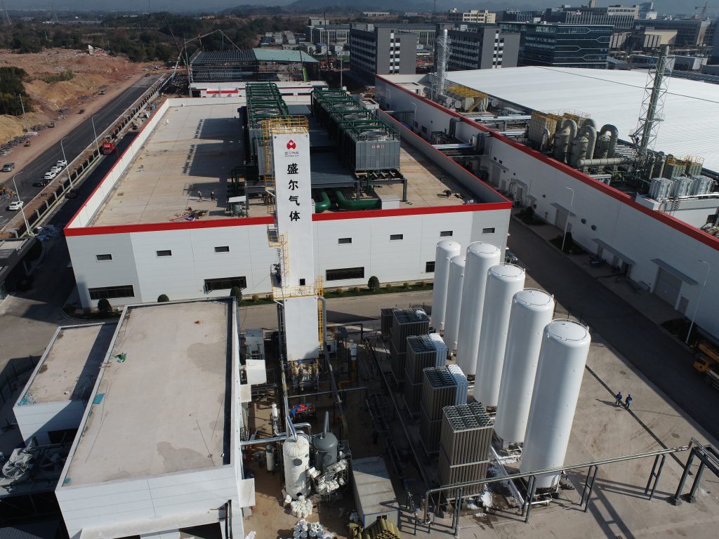
Figure: Exterior view of a cryogenic air separation plant (Linde facility, West Virginia, USA).
Industrial Applications
Cryogenic ASUs operate on-site in steel mills, petrochemical complexes, and power plants. In these industries, the cryogenic air separation process supplies the required high-purity oxygen and nitrogen. For example, in steelmaking the cryogenic air separation process provides oxygen for basic oxygen furnaces and ladle burners, greatly accelerating steel production. Nitrogen from ASUs is used for molten metal inerting, pipeline purging, and cooling in steel and chemical processes.
In petrochemical plants, oxygen from ASUs supports processes such as syngas generation and oxidation reactors, while nitrogen is used for reactor feed blanketing and catalyst regeneration. In power generation, oxygen from ASUs enables oxy-fuel combustion for cleaner power and easier CO₂ capture, while nitrogen is used for turbine blade cooling and combustion control. Across all sectors, ASUs typically run continuously to meet large demand and must be highly reliable. No alternative process can economically match cryogenic ASUs for multi-component air separation at this scale and purity.
Conclusion
The cryogenic air separation process relies on fundamental cryogenic thermodynamics to produce bulk oxygen, nitrogen, and argon. By integrating multistage compression, precise purification, brazed-plate heat exchange, and counter-current distillation columns, modern ASUs convert ambient air into the industrial gases needed for steelmaking, petrochemical, and power-generation applications. Understanding the cryogenic air separation process – from inter-stage cooling and sieve drying to expander refrigeration and column reflux – is critical for engineers optimizing ASU performance.


