Through the combination of recuperative heat exchange in the MHE and the cooling power of the expansion turbine, the air separation unit brings the process air to cryogenic conditions. At this point, a significant portion of the air is in liquid phase (typically a mixture of liquid oxygen, liquid nitrogen, and liquefied argon-rich components). The stage is set for the cryogenic distillation in the cold box where the separation into pure oxygen and nitrogen is completed.
Cryogenic Distillation in the Cold Box
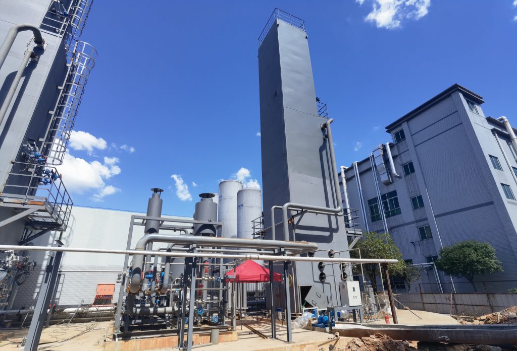
The heart of a cryogenic air separation unit is the cold box, an insulated cryogenic distillation system where the actual separation of oxygen and nitrogen (and argon) occurs. The cold box typically contains two main distillation columns as described earlier – a High-Pressure (HP) column and a Low-Pressure (LP) column – arranged in a double-column configuration. These columns are constructed with trays or structured packing and are housed in a tall insulated enclosure (the “cold box”) to minimize heat gain. The entire cold box is often filled with perlite insulation or kept under vacuum to maintain the cryogenic environment.
Here’s how the distillation works in practice: The incoming high-pressure air (partially liquefied from the MHE and expander cooling) is fed into the bottom section of the high-pressure column. As this feed mixture contacts the rising vapor and falling liquid inside the HP column, nitrogen (the more volatile component) tends to go upward and oxygen (less volatile) concentrates in the liquid downward. The high-pressure column operates at around 5–6 bar, which means its internal temperature levels are a bit warmer than at 1 bar (the boiling points of gases increase with pressure). For example, at 6 bar, nitrogen might condense around –170 °C or warmer. The HP column produces two output streams: (1) an oxygen-enriched liquid at the bottom (often 35–40% O₂, with the balance being N₂ and Ar), and (2) nearly pure nitrogen gas at the top (often 99+% N₂, with small O₂ impurity). In some ASU designs, a portion of this high-pressure nitrogen gas can be withdrawn directly from the top of the HP column as a product stream (especially if high-pressure nitrogen product is needed). Otherwise – and in most large ASUs – the nitrogen top vapor is routed to the next step of the process within the cold box.
The nitrogen-rich vapor from the HP column top is led into the main condenser/reboiler unit, which sits at the bottom of the low-pressure column. This heat exchanger (usually a thermosiphon reboiler) condenses the high-pressure nitrogen by cooling it against boiling liquid oxygen in the low-pressure column. In doing so, it boils the oxygen-rich liquid in the low-pressure column sump, generating upward vapor flow in the LP column. The condensed nitrogen (now liquid at low-pressure column pressure) serves as reflux for both columns: a portion of this liquid nitrogen is returned to the top of the HP column as reflux to maintain the HP column separation, and another portion is fed to the top of the low-pressure column as the reflux stream for the LP column. This arrangement effectively couples the two columns: the HP column provides the reflux liquid and cooling duty for the LP column, while the LP column’s boiling provides the load that condenses the HP column’s vapor.
Now in the Low-Pressure column (operating near 1.0–1.3 bar), the separation between oxygen and nitrogen is refined to completion. The feed to the LP column consists of the throttled oxygen-rich liquid from the HP column (introduced near an intermediate stage of the LP column) and the liquid nitrogen reflux at the top. As these flow down and up respectively, the LP column acts to strip out the remaining nitrogen from the oxygen-rich liquid and to strip oxygen out of the rising vapor. At the top of the low-pressure column, high-purity gaseous nitrogen emerges – typically containing only a few ppm of oxygen. This cold gaseous N₂ top product is withdrawn and sent back through the main heat exchanger to be warmed (yielding the final gaseous nitrogen product stream). At the bottom of the LP column, nearly pure liquid oxygen collects in the reboiler sump. This liquid oxygen is usually ~99.5% O₂ (with argon as the principal impurity, if argon is not fully extracted). It is withdrawn as the crude liquid oxygen product. If high-pressure gaseous oxygen is the desired end product, the LOX from the column will be pumped and vaporized (described in the next section). If low-pressure liquid oxygen is needed, it can be taken directly to storage.
The low-pressure column also generates a waste gas stream – not all the nitrogen is sent to product, especially if the plant is designed primarily for oxygen production. This waste gas (essentially nitrogen with trace argon/oxygen) is typically drawn from an upper section of the LP column. A portion of it may be used internally (for example, as the regeneration gas for the PPU adsorbers, after being warmed). The rest is ultimately vented to atmosphere as nitrogen-rich exhaust. Because the waste gas is expanded to near ambient pressure in the LP column and then warmed in the main heat exchanger, it provides cooling duty and exits the ASU near ambient temperature.
For plants with an argon recovery system, an argon-rich vapor side-draw is taken from the low-pressure column at the height where the concentration of argon is highest (typically where the liquid is ~10–12% O₂, which corresponds to ~~ 80% Ar, since argon concentrates at that point). This stream is sent to a smaller argon distillation column (within the cold box) operating at low pressure. The argon column produces crude argon (~98% Ar, ~2% O₂) as overhead and liquid oxygen (which returns to the main LP column) as bottoms. The crude argon can then be purified in auxiliary steps (as mentioned earlier) if pure argon product is desired. Argon production is an important design option but adds complexity; if argon is not needed, the argon simply remains with the oxygen product. In many ASUs, argon is recovered both to improve oxygen purity and to provide a valuable third product.
In summary, the cold box’s distillation system – comprising the double-column (HP and LP) and optional argon column – is where the cooled air is separated into oxygen and nitrogen. The design of these columns (diameter, height, internal configuration) is a key part of ASU engineering, ensuring the required purity and recovery are met. The columns operate continuously at steady state, and their performance is controlled via reflux ratios, feed conditions, and heat integration. With the separation complete, the next step is to send the products to storage or pipeline delivery in the desired state (gas or liquid).
Product Warming and Delivery
After distillation, the separated oxygen and nitrogen products are obtained at cryogenic temperatures and need to be delivered to end use at required conditions. In a typical cryogenic air separation unit, product oxygen and nitrogen are withdrawn from the cold box and warmed up to ambient temperature via the main heat exchanger (or dedicated product vaporizers). This not only recovers valuable cold (as discussed) but also ensures the gases are delivered warm and dry, suitable for pipelines and process usage (most applications use gaseous products at near ambient temperature, except when filling liquid storage). By the time the O₂ and N₂ streams leave the main heat exchanger, they are roughly at ambient conditions (~20 °C), having relinquished their cold energy to incoming air.
The delivery pressure of the products depends on user requirements. If the customer needs low-pressure gases (for example, some processes can use oxygen just above atmospheric pressure), the gases may be delivered directly from the low-pressure column output. In many industrial cases, however, oxygen and nitrogen are needed at several barg of pressure (e.g. 5–10 bar for pipeline distribution to a steel mill or chemical plant). There are a couple of design approaches to meet this:
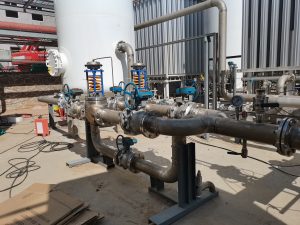
- For oxygen: Often the liquid oxygen collected at the bottom of the LP column is pumped to a higher pressure by a cryogenic liquid pump and then evaporated by heat exchange. This approach is very efficient because pumping a liquid requires far less energy than compressing a gas. The LOX may be pumped to the desired delivery pressure (even tens of bar, if needed) and then vaporized by exchanging heat with a warmer stream (often against incoming air in the main heat exchanger, or in a separate vaporizer unit). The result is high-pressure gaseous oxygen delivered to the product pipeline. If only low-pressure gaseous oxygen is required, the LOX can simply be gravity-fed to a reboiler and boiled off at the low-pressure column pressure, then boosted by a blower or compressor if needed. But in modern large ASUs, pumping and vaporizing is the preferred method for high-pressure O₂ product.
- For nitrogen: Gaseous nitrogen is produced at the top of the low-pressure column, essentially at near 1 bar. If moderate pressure gaseous nitrogen is required (say 5–6 bar), one convenient method is to take a side stream of nitrogen from the high-pressure column instead – the HP column’s overhead gas is already at ~6 bar and high purity, so it can be sent out directly as product after cooling. Some ASUs are designed to provide product nitrogen from the HP column in this way (with appropriate cooling to ambient). Alternatively, nitrogen gas from the LP column can be compressed by a product compressor to the required pressure after it is warmed. If very high pressure nitrogen is needed or if liquid nitrogen product is desired, a portion of the condensed liquid nitrogen from the cold box can be subcooled and sent to storage tanks or pumped and vaporized similar to the oxygen approach.
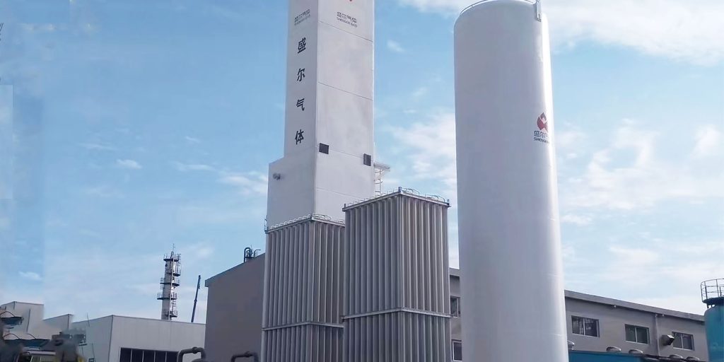
Many large air separation facilities produce both gas and liquid products. For example, they might supply gaseous oxygen by pipeline continuously, while also producing liquid oxygen, liquid nitrogen (and liquid argon) for storage in cryogenic tanks. These liquid products can be transported in insulated tanker trucks to off-site customers. An ASU can be adjusted to produce extra liquid product by taking more reflux as liquid and sending it to storage instead of back into the columns, effectively liquefying a portion of the output. This flexibility is another design aspect – balancing gas output vs. liquid draw – that operators manage based on demand.
Importantly, before final delivery, the gaseous products pass through quality control measures. Analyzers monitor oxygen purity (to ensure O₂ is at spec, e.g. 99.5% or whatever the requirement) and trace contaminants. Nitrogen product is analyzed for residual O₂ (often needing to be below a few ppm for high-purity N₂). The product streams are also typically metered and then introduced into pipelines or filled into cylinders/liquid containers as needed.
Typical Performance and Operating Conditions
Modern cryogenic air separation units are impressively large and efficient, operating continuously to generate thousands of tons of product per day. Table 1 summarizes some typical performance parameters for oxygen and nitrogen production from a large industrial cryogenic ASU.
Table 1: Typical purity, pressure, and temperature characteristics for O₂ and N₂ outputs from a cryogenic ASU
| Parameter | Oxygen (O₂) | Nitrogen (N₂) |
|---|---|---|
| Product Purity (vol %) | ~99.5% (high-purity) | ~99.999% (ultra-high) |
| Delivery Pressure (gas) | ~5–6 bar (typical pipeline supply) | ~5–6 bar (typical pipeline supply) |
| Boiling Point at 1 atm (°C) | –183 °C | –196 °C |
As shown above, cryogenic ASUs routinely produce oxygen ~99.5% pure by volume (the remaining 0.5% is mostly argon, with only ppm levels of nitrogen). Nitrogen product from a double-column ASU can reach 99.999% purity, meaning oxygen content in the nitrogen is extremely low (only a few parts per million O₂). The delivery pressure for gaseous products is often on the order of a few bar above atmospheric pressure – around 5 bar is common for pipeline distribution to industrial users. Internally, the process involves higher pressures (the air is compressed to ~6 bar and the high-pressure column operates at that level) and low pressures (the low-pressure column at ~1.2 bar). The cryogenic temperature range is roughly from ambient down to –185 °C (in the high-pressure column and main heat exchanger) and as low as –196 °C at the nitrogen top end. These extremely low temperatures necessitate specialized materials and good insulation in the cold box.
Cryogenic ASUs are energy-intensive systems, largely due to the work of air compression and the need for refrigeration. A well-designed large ASU might consume around 0.3–0.6 kWh of electricity per Nm³ of O₂ produced (this is equivalent to roughly 200–400 kWh per ton of O₂). The energy consumption per unit of product tends to improve (lower) with larger plant capacities, due to economies of scale and more efficient turbines and heat exchangers. Despite the high power usage, cryogenic air separation is usually the most economical method for producing very large quantities of oxygen and nitrogen; the specific energy per unit mass of product becomes quite low at scale, and the high purity and reliability justify the process in heavy industrial applications.
Design Considerations and Process Engineering Aspects
From a process engineering perspective, cryogenic air separation units involve careful design trade-offs to meet performance, efficiency, and safety requirements. Some key design and operational considerations include:
- Energy Efficiency: Because compression and refrigeration dominate the power consumption, modern ASUs are designed to maximize heat integration and recover as much cold energy as possible. The main heat exchanger is engineered for very close approach temperatures, minimizing wasted cold. Expansion turbines are used to recover work (often driving compressors within the cycle). Cycle configurations (for instance, whether to take product from the high-pressure column or to pump liquid products) are chosen based on minimizing overall energy usage for the required product mix and pressure. Engineering advancements continue to improve compressor efficiency (e.g., aerodynamic optimization of air compressor stages) and heat exchanger performance, which incrementally reduce the kilowatt hours per unit of gas produced. Some large plants also integrate with power systems – for example, using expander-generated energy to feed into the plant’s electrical network or to run ancillary equipment.
- Product Pressure vs. Power Trade-off: An important design decision is how to deliver the required product pressure. Operating the entire ASU at higher pressure (e.g. a 8–10 bar cycle instead of ~6 bar) can produce gases at higher pressure directly from the columns, potentially avoiding the need for product compressors or liquid pumping. However, running everything at higher pressure increases the compressor work and thus energy consumption significantly. On the other hand, a low-pressure cycle (near 5 bar) with liquid pumping to achieve product pressure is often more efficient but introduces cryogenic pumps and vaporizers. Engineers must evaluate the most economical approach based on the desired output pressure: for moderate pressures, pumping LOX and LIN is usually more energy-efficient; for extremely high pressures or certain configurations, multi-stage product compressors might be used. The optimal cycle is tailored to the product requirements to minimize both capital and operating costs.
- Safety and Materials: Cryogenic ASUs handle large volumes of oxygen at high purity and in concentrated form – an oxygen-rich environment poses fire and explosion hazards if any organic material or spark is present. Hence, ASU design pays special attention to materials of construction and cleanliness. All equipment in oxygen service (cold box internals, piping, valves) is made of materials compatible with high-purity O₂ (typically stainless steels, aluminum, copper alloys) and cleaned thoroughly to remove any traces of hydrocarbons, oils, or other combustibles. Hydrocarbon monitoring systems are often installed to detect any accumulation of hydrocarbons in the liquid oxygen sump, since a flammable hydrocarbon in liquid O₂ is a serious hazard. If readings approach unsafe limits, the plant will initiate preventive measures (like controlled venting or warm-up) to remove contaminants. Additionally, the argon side draw helps limit hydrocarbon concentration in the main columns (since most hydrocarbons are more volatile than O₂ and tend to concentrate where argon does). Pressure relief and control systems are also critical – the cold box and heat exchangers are protected by safety valves, and the columns have systems to prevent overpressure or unsafe temperatures.
- Operational Flexibility and Control: Modern cryogenic air separation units are equipped with advanced control systems that allow them to adjust production rates and ratios of O₂/N₂ (and argon) to some extent. By manipulating parameters like air flow rate, turbine expansion flow, and reflux ratios, operators can optimize the plant for current demand or for efficiency. For example, if the demand for oxygen drops, the ASU can shift to produce more liquid product for storage or reduce power consumption by throttling back compressors (within limits, since ASUs prefer steady operation). Automation systems ensure tight control of column pressures, liquid levels, and purity analyzers to keep the unit running safely and optimally. Start-up and shut-down procedures for ASUs are complex and carefully engineered, as thermal stresses and moisture ingress must be managed; larger plants often keep a backup liquid supply to help manage transitions or supply customers during ramp-ups.
- Scale and Modular Design: Air separation units can be designed for a wide range of capacities – from small units producing a few tens of tons per day of oxygen (often skid-mounted packaged plants) to gigantic complexes producing over 4,000 tons per day of O₂. At the high end, multiple cold boxes and parallel trains might be used for capacity or redundancy. Scale-up is not simply a linear process; engineers must account for factors like column diameter limitations, optimal air compressor sizing, and transportation limits for large equipment. Often, very large ASUs are built with multiple identical trains for ease of construction and operation. Modular cold box construction is common: the distillation columns and heat exchangers are assembled inside a large rectangular cold box at the factory, which is then transported to site and connected to compressors and utilities.
In conclusion, cryogenic air separation units remain the state-of-the-art technology for producing oxygen and nitrogen at high purity and large scale. They exemplify a highly integrated process: combining compression, cryogenic refrigeration, and multi-column distillation to achieve an efficient separation. The process discussed – compressing air, purifying it, cooling to cryogenic temperatures via heat exchangers and expansion turbines, and distilling in a double-column system – enables production of gaseous oxygen and nitrogen that underpin countless industrial operations. While energy-intensive, ongoing innovations in heat exchanger design, rotating machinery efficiency, and process control are continually improving the performance of these units. Equally, the engineering emphasis on safety and reliability has made modern ASUs extremely dependable, often running for years with minimal downtime. For process engineers and designers, the cryogenic ASU is a fascinating system where thermodynamics, fluid dynamics, and real-world operational considerations intersect. With growing global demand for industrial gases and emerging applications (like oxygen for clean combustion or large-scale nitrogen for electronics and food preservation), cryogenic air separation units will continue to play a critical role – delivering oxygen and nitrogen in the volumes and purities that advanced industries require, efficiently and safely.
antly, the expanded cold gas provides the necessary refrigeration to the process: the expanded stream may be injected into the cold box to help liquefy incoming air or used to provide cooling duty in the heat exchanger. By using an expansion turbine rather than a simple Joule-Thomson throttling valve, the ASU can reach cryogenic temperatures with far less entropy generation, yielding a colder stream and additional useful work.
Through the combination of recuperative heat exchange in the MHE and the cooling power of the expansion turbine, the air separation unit brings the process air to cryogenic conditions. At this point, a significant portion of the air is in liquid phase (typically a mixture of liquid oxygen, liquid nitrogen, and liquefied argon-rich components). The stage is set for the cryogenic distillation in the cold box where the separation into pure oxygen and nitrogen is completed.
Cryogenic Distillation in the Cold Box
The heart of a cryogenic air separation unit is the cold box, an insulated cryogenic distillation system where the actual separation of oxygen and nitrogen (and argon) occurs. The cold box typically contains two main distillation columns as described earlier – a High-Pressure (HP) column and a Low-Pressure (LP) column – arranged in a double-column configuration. These columns are constructed with trays or structured packing and are housed in a tall insulated enclosure (the “cold box”) to minimize heat gain. The entire cold box is often filled with perlite insulation or kept under vacuum to maintain the cryogenic environment.
Here’s how the distillation works in practice: The incoming high-pressure air (partially liquefied from the MHE and expander cooling) is fed into the bottom section of the high-pressure column. As this feed mixture contacts the rising vapor and falling liquid inside the HP column, nitrogen (the more volatile component) tends to go upward and oxygen (less volatile) concentrates in the liquid downward. The high-pressure column operates at around 5–6 bar, which means its internal temperature levels are a bit warmer than at 1 bar (the boiling points of gases increase with pressure). For example, at 6 bar, nitrogen might condense around –170 °C or warmer. The HP column produces two output streams: (1) an oxygen-enriched liquid at the bottom (often 35–40% O₂, with the balance being N₂ and Ar), and (2) nearly pure nitrogen gas at the top (often 99+% N₂, with small O₂ impurity). In some ASU designs, a portion of this high-pressure nitrogen gas can be withdrawn directly from the top of the HP column as a product stream (especially if high-pressure nitrogen product is needed). Otherwise – and in most large ASUs – the nitrogen top vapor is routed to the next step of the process within the cold box.
The nitrogen-rich vapor from the HP column top is led into the main condenser/reboiler unit, which sits at the bottom of the low-pressure column. This heat exchanger (usually a thermosiphon reboiler) condenses the high-pressure nitrogen by cooling it against boiling liquid oxygen in the low-pressure column. In doing so, it boils the oxygen-rich liquid in the low-pressure column sump, generating upward vapor flow in the LP column. The condensed nitrogen (now liquid at low-pressure column pressure) serves as reflux for both columns: a portion of this liquid nitrogen is returned to the top of the HP column as reflux to maintain the HP column separation, and another portion is fed to the top of the low-pressure column as the reflux stream for the LP column. This arrangement effectively couples the two columns: the HP column provides the reflux liquid and cooling duty for the LP column, while the LP column’s boiling provides the load that condenses the HP column’s vapor.
Now in the Low-Pressure column (operating near 1.0–1.3 bar), the separation between oxygen and nitrogen is refined to completion. The feed to the LP column consists of the throttled oxygen-rich liquid from the HP column (introduced near an intermediate stage of the LP column) and the liquid nitrogen reflux at the top. As these flow down and up respectively, the LP column acts to strip out the remaining nitrogen from the oxygen-rich liquid and to strip oxygen out of the rising vapor. At the top of the low-pressure column, high-purity gaseous nitrogen emerges – typically containing only a few ppm of oxygen. This cold gaseous N₂ top product is withdrawn and sent back through the main heat exchanger to be warmed (yielding the final gaseous nitrogen product stream). At the bottom of the LP column, nearly pure liquid oxygen collects in the reboiler sump. This liquid oxygen is usually ~99.5% O₂ (with argon as the principal impurity, if argon is not fully extracted). It is withdrawn as the crude liquid oxygen product. If high-pressure gaseous oxygen is the desired end product, the LOX from the column will be pumped and vaporized (described in the next section). If low-pressure liquid oxygen is needed, it can be taken directly to storage.
The low-pressure column also generates a waste gas stream – not all the nitrogen is sent to product, especially if the plant is designed primarily for oxygen production. This waste gas (essentially nitrogen with trace argon/oxygen) is typically drawn from an upper section of the LP column. A portion of it may be used internally (for example, as the regeneration gas for the PPU adsorbers, after being warmed). The rest is ultimately vented to atmosphere as nitrogen-rich exhaust. Because the waste gas is expanded to near ambient pressure in the LP column and then warmed in the main heat exchanger, it provides cooling duty and exits the ASU near ambient temperature.
For plants with an argon recovery system, an argon-rich vapor side-draw is taken from the low-pressure column at the height where the concentration of argon is highest (typically where the liquid is ~10–12% O₂, which corresponds to ~~ 80% Ar, since argon concentrates at that point). This stream is sent to a smaller argon distillation column (within the cold box) operating at low pressure. The argon column produces crude argon (~98% Ar, ~2% O₂) as overhead and liquid oxygen (which returns to the main LP column) as bottoms. The crude argon can then be purified in auxiliary steps (as mentioned earlier) if pure argon product is desired. Argon production is an important design option but adds complexity; if argon is not needed, the argon simply remains with the oxygen product. In many ASUs, argon is recovered both to improve oxygen purity and to provide a valuable third product.
In summary, the cold box’s distillation system – comprising the double-column (HP and LP) and optional argon column – is where the cooled air is separated into oxygen and nitrogen. The design of these columns (diameter, height, internal configuration) is a key part of ASU engineering, ensuring the required purity and recovery are met. The columns operate continuously at steady state, and their performance is controlled via reflux ratios, feed conditions, and heat integration. With the separation complete, the next step is to send the products to storage or pipeline delivery in the desired state (gas or liquid).
Product Warming and Delivery
After distillation, the separated oxygen and nitrogen products are obtained at cryogenic temperatures and need to be delivered to end use at required conditions. In a typical cryogenic air separation unit, product oxygen and nitrogen are withdrawn from the cold box and warmed up to ambient temperature via the main heat exchanger (or dedicated product vaporizers). This not only recovers valuable cold (as discussed) but also ensures the gases are delivered warm and dry, suitable for pipelines and process usage (most applications use gaseous products at near ambient temperature, except when filling liquid storage). By the time the O₂ and N₂ streams leave the main heat exchanger, they are roughly at ambient conditions (~20 °C), having relinquished their cold energy to incoming air.
The delivery pressure of the products depends on user requirements. If the customer needs low-pressure gases (for example, some processes can use oxygen just above atmospheric pressure), the gases may be delivered directly from the low-pressure column output. In many industrial cases, however, oxygen and nitrogen are needed at several barg of pressure (e.g. 5–10 bar for pipeline distribution to a steel mill or chemical plant). There are a couple of design approaches to meet this:
- For oxygen: Often the liquid oxygen collected at the bottom of the LP column is pumped to a higher pressure by a cryogenic liquid pump and then evaporated by heat exchange. This approach is very efficient because pumping a liquid requires far less energy than compressing a gas. The LOX may be pumped to the desired delivery pressure (even tens of bar, if needed) and then vaporized by exchanging heat with a warmer stream (often against incoming air in the main heat exchanger, or in a separate vaporizer unit). The result is high-pressure gaseous oxygen delivered to the product pipeline. If only low-pressure gaseous oxygen is required, the LOX can simply be gravity-fed to a reboiler and boiled off at the low-pressure column pressure, then boosted by a blower or compressor if needed. But in modern large ASUs, pumping and vaporizing is the preferred method for high-pressure O₂ product.
- For nitrogen: Gaseous nitrogen is produced at the top of the low-pressure column, essentially at near 1 bar. If moderate pressure gaseous nitrogen is required (say 5–6 bar), one convenient method is to take a side stream of nitrogen from the high-pressure column instead – the HP column’s overhead gas is already at ~6 bar and high purity, so it can be sent out directly as product after cooling. Some ASUs are designed to provide product nitrogen from the HP column in this way (with appropriate cooling to ambient). Alternatively, nitrogen gas from the LP column can be compressed by a product compressor to the required pressure after it is warmed. If very high pressure nitrogen is needed or if liquid nitrogen product is desired, a portion of the condensed liquid nitrogen from the cold box can be subcooled and sent to storage tanks or pumped and vaporized similar to the oxygen approach.
Many large air separation facilities produce both gas and liquid products. For example, they might supply gaseous oxygen by pipeline continuously, while also producing liquid oxygen, liquid nitrogen (and liquid argon) for storage in cryogenic tanks. These liquid products can be transported in insulated tanker trucks to off-site customers. An ASU can be adjusted to produce extra liquid product by taking more reflux as liquid and sending it to storage instead of back into the columns, effectively liquefying a portion of the output. This flexibility is another design aspect – balancing gas output vs. liquid draw – that operators manage based on demand.
Importantly, before final delivery, the gaseous products pass through quality control measures. Analyzers monitor oxygen purity (to ensure O₂ is at spec, e.g. 99.5% or whatever the requirement) and trace contaminants. Nitrogen product is analyzed for residual O₂ (often needing to be below a few ppm for high-purity N₂). The product streams are also typically metered and then introduced into pipelines or filled into cylinders/liquid containers as needed.
Typical Performance and Operating Conditions
Modern cryogenic air separation units are impressively large and efficient, operating continuously to generate thousands of tons of product per day. Table 1 summarizes some typical performance parameters for oxygen and nitrogen production from a large industrial cryogenic ASU.
Table 1: Typical purity, pressure, and temperature characteristics for O₂ and N₂ outputs from a cryogenic ASU
| Parameter | Oxygen (O₂) | Nitrogen (N₂) |
|---|---|---|
| Product Purity (vol %) | ~99.5% (high-purity) | ~99.999% (ultra-high) |
| Delivery Pressure (gas) | ~5–6 bar (typical pipeline supply) | ~5–6 bar (typical pipeline supply) |
| Boiling Point at 1 atm (°C) | –183 °C | –196 °C |
As shown above, cryogenic ASUs routinely produce oxygen ~99.5% pure by volume (the remaining 0.5% is mostly argon, with only ppm levels of nitrogen). Nitrogen product from a double-column ASU can reach 99.999% purity, meaning oxygen content in the nitrogen is extremely low (only a few parts per million O₂). The delivery pressure for gaseous products is often on the order of a few bar above atmospheric pressure – around 5 bar is common for pipeline distribution to industrial users. Internally, the process involves higher pressures (the air is compressed to ~6 bar and the high-pressure column operates at that level) and low pressures (the low-pressure column at ~1.2 bar). The cryogenic temperature range is roughly from ambient down to –185 °C (in the high-pressure column and main heat exchanger) and as low as –196 °C at the nitrogen top end. These extremely low temperatures necessitate specialized materials and good insulation in the cold box.
Cryogenic ASUs are energy-intensive systems, largely due to the work of air compression and the need for refrigeration. A well-designed large ASU might consume around 0.3–0.6 kWh of electricity per Nm³ of O₂ produced (this is equivalent to roughly 200–400 kWh per ton of O₂). The energy consumption per unit of product tends to improve (lower) with larger plant capacities, due to economies of scale and more efficient turbines and heat exchangers. Despite the high power usage, cryogenic air separation is usually the most economical method for producing very large quantities of oxygen and nitrogen; the specific energy per unit mass of product becomes quite low at scale, and the high purity and reliability justify the process in heavy industrial applications.
Design Considerations and Process Engineering Aspects
From a process engineering perspective, cryogenic air separation units involve careful design trade-offs to meet performance, efficiency, and safety requirements. Some key design and operational considerations include:
- Energy Efficiency: Because compression and refrigeration dominate the power consumption, modern ASUs are designed to maximize heat integration and recover as much cold energy as possible. The main heat exchanger is engineered for very close approach temperatures, minimizing wasted cold. Expansion turbines are used to recover work (often driving compressors within the cycle). Cycle configurations (for instance, whether to take product from the high-pressure column or to pump liquid products) are chosen based on minimizing overall energy usage for the required product mix and pressure. Engineering advancements continue to improve compressor efficiency (e.g., aerodynamic optimization of air compressor stages) and heat exchanger performance, which incrementally reduce the kilowatt hours per unit of gas produced. Some large plants also integrate with power systems – for example, using expander-generated energy to feed into the plant’s electrical network or to run ancillary equipment.
- Product Pressure vs. Power Trade-off: An important design decision is how to deliver the required product pressure. Operating the entire ASU at higher pressure (e.g. a 8–10 bar cycle instead of ~6 bar) can produce gases at higher pressure directly from the columns, potentially avoiding the need for product compressors or liquid pumping. However, running everything at higher pressure increases the compressor work and thus energy consumption significantly. On the other hand, a low-pressure cycle (near 5 bar) with liquid pumping to achieve product pressure is often more efficient but introduces cryogenic pumps and vaporizers. Engineers must evaluate the most economical approach based on the desired output pressure: for moderate pressures, pumping LOX and LIN is usually more energy-efficient; for extremely high pressures or certain configurations, multi-stage product compressors might be used. The optimal cycle is tailored to the product requirements to minimize both capital and operating costs.
- Safety and Materials: Cryogenic ASUs handle large volumes of oxygen at high purity and in concentrated form – an oxygen-rich environment poses fire and explosion hazards if any organic material or spark is present. Hence, ASU design pays special attention to materials of construction and cleanliness. All equipment in oxygen service (cold box internals, piping, valves) is made of materials compatible with high-purity O₂ (typically stainless steels, aluminum, copper alloys) and cleaned thoroughly to remove any traces of hydrocarbons, oils, or other combustibles. Hydrocarbon monitoring systems are often installed to detect any accumulation of hydrocarbons in the liquid oxygen sump, since a flammable hydrocarbon in liquid O₂ is a serious hazard. If readings approach unsafe limits, the plant will initiate preventive measures (like controlled venting or warm-up) to remove contaminants. Additionally, the argon side draw helps limit hydrocarbon concentration in the main columns (since most hydrocarbons are more volatile than O₂ and tend to concentrate where argon does). Pressure relief and control systems are also critical – the cold box and heat exchangers are protected by safety valves, and the columns have systems to prevent overpressure or unsafe temperatures.
- Operational Flexibility and Control: Modern cryogenic air separation units are equipped with advanced control systems that allow them to adjust production rates and ratios of O₂/N₂ (and argon) to some extent. By manipulating parameters like air flow rate, turbine expansion flow, and reflux ratios, operators can optimize the plant for current demand or for efficiency. For example, if the demand for oxygen drops, the ASU can shift to produce more liquid product for storage or reduce power consumption by throttling back compressors (within limits, since ASUs prefer steady operation). Automation systems ensure tight control of column pressures, liquid levels, and purity analyzers to keep the unit running safely and optimally. Start-up and shut-down procedures for ASUs are complex and carefully engineered, as thermal stresses and moisture ingress must be managed; larger plants often keep a backup liquid supply to help manage transitions or supply customers during ramp-ups.
- Scale and Modular Design: Air separation units can be designed for a wide range of capacities – from small units producing a few tens of tons per day of oxygen (often skid-mounted packaged plants) to gigantic complexes producing over 4,000 tons per day of O₂. At the high end, multiple cold boxes and parallel trains might be used for capacity or redundancy. Scale-up is not simply a linear process; engineers must account for factors like column diameter limitations, optimal air compressor sizing, and transportation limits for large equipment. Often, very large ASUs are built with multiple identical trains for ease of construction and operation. Modular cold box construction is common: the distillation columns and heat exchangers are assembled inside a large rectangular cold box at the factory, which is then transported to site and connected to compressors and utilities.
In conclusion, cryogenic air separation units remain the state-of-the-art technology for producing oxygen and nitrogen at high purity and large scale. They exemplify a highly integrated process: combining compression, cryogenic refrigeration, and multi-column distillation to achieve an efficient separation. The process discussed – compressing air, purifying it, cooling to cryogenic temperatures via heat exchangers and expansion turbines, and distilling in a double-column system – enables production of gaseous oxygen and nitrogen that underpin countless industrial operations. While energy-intensive, ongoing innovations in heat exchanger design, rotating machinery efficiency, and process control are continually improving the performance of these units. Equally, the engineering emphasis on safety and reliability has made modern ASUs extremely dependable, often running for years with minimal downtime. For process engineers and designers, the cryogenic ASU is a fascinating system where thermodynamics, fluid dynamics, and real-world operational considerations intersect. With growing global demand for industrial gases and emerging applications (like oxygen for clean combustion or large-scale nitrogen for electronics and food preservation), cryogenic air separation units will continue to play a critical role – delivering oxygen and nitrogen in the volumes and purities that advanced industries require, efficiently and safely.