Cryogenic Nitrogen Production is the process of generating high-purity nitrogen gas by separating it from ambient air at extremely low temperatures. This method relies on the fact that nitrogen and oxygen liquefy at different cryogenic temperatures (nitrogen at –196 °C and oxygen at –183 °C), enabling their separation in a distillation column. In a typical cryogenic air separation unit (ASU), filtered air (about 78% N₂, 21% O₂) is compressed and then expanded or cooled through heat exchangers to roughly –180 °C, causing the air to partially liquefy. Because nitrogen boils at a lower temperature, it vaporizes out of the cold liquid first, yielding nearly pure N₂ gas at the top of the column. This process enables production of nitrogen at purities from ~99.5% up to 99.999% or higher, making it suitable for demanding industrial applications.
Cryogenic Nitrogen Production Process
- Air Compression and Purification: Ambient air is drawn in and compressed (multi-stage) to moderate pressures (typically 5–10 bar) before cooling. Coarse filtration, refrigerated cooling, and molecular sieve adsorbers remove moisture, CO₂, and hydrocarbons to protect downstream equipment.
- Cryogenic Cooling: The purified, high-pressure air is passed through counter-flow heat exchangers and expansion turbines (turbo-expanders or Joule–Thomson valves) to reach cryogenic temperatures (~–180 °C). At these conditions, heavier impurities freeze out, and the air forms a cold liquid–vapor mixture.
- Fractional Distillation: The cold air enters one or more distillation columns. Nitrogen, which boils at –196 °C, vaporizes and rises to the top of the column, while oxygen (–183 °C) and other heavier components remain as liquid at the bottom. Modern plants often use a high-pressure column feeding a low-pressure column to achieve ultra-high purity and yield (with an optional argon-recovery column if needed).
- Product Collection: Pure gaseous N₂ is withdrawn from the top of the low-pressure column, warmed to ambient temperature, and delivered to the end user at pipeline pressure. A portion of liquid nitrogen (~10% of total output) is also collected and stored in insulated tanks. This stored LN₂ can be vaporized to meet peak demands or to provide backup supply.
Key Equipment in Cryogenic Nitrogen Production
- Air Compressor: A multi-stage reciprocating or centrifugal compressor increases the pressure of incoming air to the ~5–10 bar range. Intercoolers between stages remove heat and help condense water vapor.
- Air Purification System: Downstream of compression, air passes through coalescing filters and molecular sieve dryers (typically twin-bed TSA) that remove water, CO₂, and oil to prevent freezing in the cryogenic section.
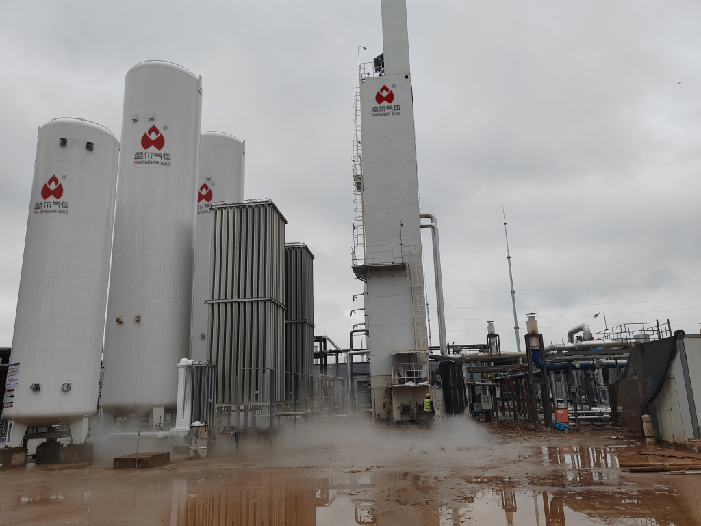
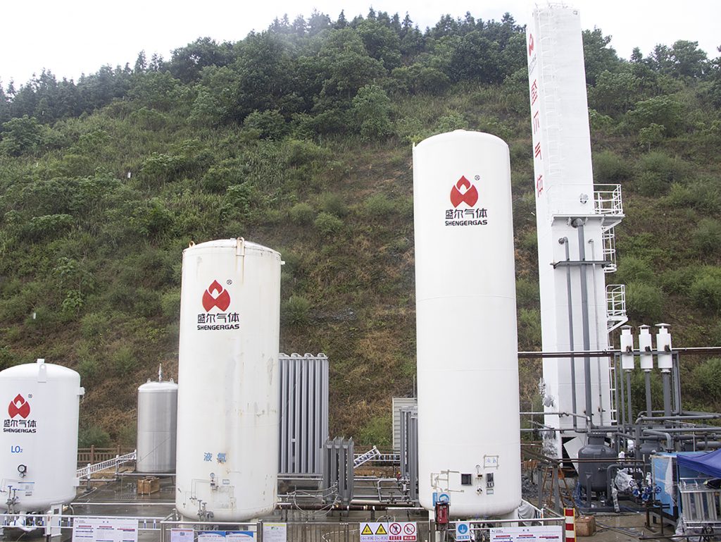
- Cryogenic Heat Exchanger (Cold Box): A key component is a cryogenic cold box containing plate-fin or coil heat exchangers. These allow staged heat exchange between incoming warm air and outgoing cold product streams, gradually cooling the process air to around –180 °C.
- Expansion Turbines (Turbo-expanders): Joule–Thomson valves and turbo-expanders provide additional cooling by expanding high-pressure air or nitrogen. Turbo-expanders often drive a booster compressor on the oxygen loop while producing refrigeration for the process.
- Distillation Columns: The heart of the separation, usually two columns (high-pressure and low-pressure), made of insulated stainless steel. The high-pressure column produces oxygen-rich liquid and nitrogen-rich vapor, which feed the low-pressure column. The low-pressure column then yields high-purity nitrogen vapor at its top.
- Booster Compressors & Pumps: Pressure let-downs and pumps adjust product pressures. For example, a small booster can raise liquid oxygen pressure, while a vaporizer (heat exchanger with steam or warm water) converts stored liquid nitrogen back to gas on demand.
- Storage and Product Handling: Insulated cryogenic tanks store liquid nitrogen, which can be vaporized as needed to meet peak demand. Control valves and pressure regulators ensure the nitrogen is delivered at the correct purity and pressure to the end-user.
Performance Parameters of Cryogenic Nitrogen Production
| Parameter | Typical Value (Cryogenic N₂ Plant) |
|---|---|
| Nitrogen Purity (vol %) | ~99.5% – 99.999% |
| Flow Rate (N₂, Nm³/hr) | ~5,000 – 60,000 (large-scale) |
| Delivery Pressure (bar) | 4 – 6 (typical pipeline delivery) |
| Specific Energy (kWh/Nm³) | ~0.3 – 0.5 (for N₂ production) |
| ASU Capacity (O₂ output) | ~100 – 5,000+ tons/day O₂ |
This table summarizes key design parameters for cryogenic nitrogen plants. Typical modern ASUs deliver N₂ at near-100% purity and on the order of thousands of Nm³ per hour. Delivery pressures are often in the 4–6 bar range for pipeline supply. Specific power consumption is on the order of 0.3–0.5 kWh per Nm³ of nitrogen produced. Large-scale oxygen output (hundreds to thousands of tons per day) indicates correspondingly massive nitrogen production capacity.
Applications of Cryogenic Nitrogen Production
- Steel and Metals: Cryogenic N₂ is widely used in steel mills for inerting and blanketing. For example, torpedo ladles carrying molten iron are filled with nitrogen to prevent oxidation, and N₂ is bubbled through molten steel to aid mixing and homogenization.
- Chemical, Petrochemical, and Oil & Gas: Large chemical plants and refineries use N₂ for safety and process control. Nitrogen inerting protects reactors and storage tanks from hazardous atmospheres, and it is used for pipeline purging and pressure testing. Cryogenic plants often serve ammonia synthesis, petrochemical feedstock operations, and floating glass furnaces.
- Semiconductors and Electronics: The electronics industry demands ultra-high purity N₂ (five-nines or more) for processes like semiconductor wafer fabrication and display manufacturing. Cryogenic N₂ provides a constant supply of clean, dry gas for purging, cooling, and maintaining inert conditions in cleanrooms and photolithography tools.
- Food, Beverage, and Pharma: In food packaging and pharmaceutical production, N₂ is used to displace oxygen (to extend shelf life or maintain sterile environments). Cryogenic nitrogen (often vaporized from liquid) can also be used for rapid freezing or chilling of products. These industries benefit from on-site generation to ensure reliable gas quality and supply.

Operational and Economic Considerations
- High Purity and Capacity: Cryogenic nitrogen production ASUs consistently yield N₂ at ≥99.5–99.999% purity and can operate at very high flow rates (thousands of Nm³/h). The continuous 24/7 output suits large-scale process industries.
- Economies of Scale: Cryogenic plants are most economical at large scale; they become cost-effective above roughly 200–300 tons/day of O₂ output, and especially above 500 tpd. At these scales, the energy cost per unit of gas drops and the capital investment is justified by high production volume.
- Energy Consumption: Cryogenic nitrogen production is energy-intensive. Typical power demand is on the order of ~0.3–0.5 kWh per Nm³ of nitrogen, higher than membrane or PSA systems at small scales. Improving thermal integration and using efficient expanders are key ways to reduce this consumption.
- Operational Factors: Large cryogenic plants involve high capital expenditure and require skilled operation and maintenance. Their footprint and startup time are greater than PSA units. However, they also produce valuable byproducts (high-purity oxygen and argon) and can meet stringent purity and continuity requirements that simpler systems cannot.
Conclusion
In summary, cryogenic nitrogen production via air separation remains the industry standard for generating large volumes of ultra-pure nitrogen gas. These systems leverage low-temperature distillation to deliver N₂ at purities often above 99.9%, meeting stringent requirements in steelmaking, chemical processing, semiconductor fabrication, and more. While cryogenic ASUs require significant capital investment and refrigeration energy, they benefit from economies of scale (becoming efficient at multi-hundred-ton-per-day output) and provide continuous, reliable supply. Innovations such as energy recovery turbines, process optimization, and integration with variable electricity sources continue to improve efficiency. As industry demands grow, on-site cryogenic ASUs adapt through modular designs and smarter controls, ensuring that cryogenic nitrogen production remains a critical technology for plant designers and operations focused on high-purity gas production.


