The Cryogenic Air Separation Process Explained for Industrial Oxygen and Nitrogen Production is an essential industrial method for producing high-purity oxygen and nitrogen from ambient air. This Cryogenic Air Separation Process Explained for Industrial Oxygen and Nitrogen Production operates by cooling filtered air to very low temperatures until its components liquefy and then separating them by fractional distillation. Engineers and researc hers use this process for a wide range of applications – from steelmaking and chemical manufacturing to energy industries like hydrogen production, synthetic fuels, and LNG liquefaction support. In the global energy context, cryogenic air separation enables low-carbon processes (such as blue hydrogen and advanced fuel synthesis) by supplying the necessary ultra-pure gases at scale.
The process relies on differences in boiling points (oxygen at –183 °C, nitrogen at –196 °C) to separate air into components. Ambient air is first compressed (typically to 5–10 bar) and then purified to remove water, CO₂, and other impurities that could freeze. The clean, high-pressure air enters the cold box (multi-stream heat exchangers) where it is cooled by counter-flow with the cold outgoing product streams and by expansion through a turbo-expander. As the air cools to roughly –180 to –190 °C, part of it liquefies. The cold air/liquid mixture then feeds the distillation column block: a high-pressure (HP) column strips out nitrogen-rich vapor at the top and oxygen/argon-rich liquid at the bottom, and this liquid flows to a low-pressure (LP) column. In the LP column (near 1 bar), remaining nitrogen is boiled off at the top and withdrawn as nearly pure gaseous nitrogen. The bottom of the LP column yields nearly pure liquid oxygen (LOX). Argon, if needed, is recovered by drawing a side liquid from the LP column into an auxiliary argon column, which produces high-purity argon and returns the balance oxygen to the main cycle. Finally, liquid oxygen is pumped or vaporized to delivery pressure, and the nitrogen product is warmed to ambient temperature and compressed to customer specifications.
Key Components and Process Steps
The core steps of the cryogenic air separation process include:
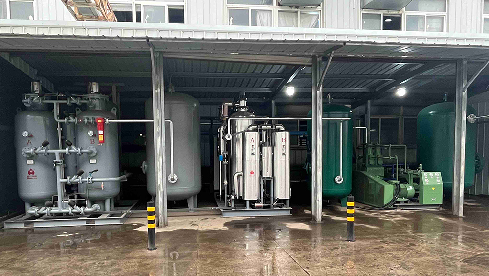
- Air Compression: Ambient air is drawn in and compressed in multiple stages (usually oil-free compressors with intercoolers). Intercoolers remove heat between stages and condense out bulk moisture. This raises the air pressure to the design distillation pressure (typically 4–8 bar), preparing it for the low-temperature separation.
- Purification: The compressed air passes through adsorbent beds (molecular sieves) or refrigeration traps to remove residual H₂O, CO₂, and hydrocarbons. These impurities must be reduced to near zero (dry, CO₂-free air) because they would otherwise freeze in the cold box and block equipment.
- Cooling and Liquefaction: The purified air enters the cold box, where it exchanges heat with outgoing product streams (liquid/gas O₂, N₂, and Ar) in multi-stream brazed-aluminum heat exchangers. A turbo-expander may produce additional refrigeration by expanding part of the air. By the end of the heat exchange, the air is typically around –180 to –190 °C and is partly liquefied. Efficient countercurrent heat integration recovers most of the refrigeration by warming the cold products against incoming warm air.
- Fractional Distillation: The cold, partly-liquid air feeds the high-pressure distillation column. In this column (operating at several bar), rising vapor carries nitrogen (bp –196 °C) out of the top while the liquid at the bottom becomes rich in oxygen and argon. That bottom liquid is sent to a lower-pressure column (near 1 atm). In the low-pressure column, rising vapors strip out the remaining nitrogen, yielding pure LOX at the bottom and nitrogen-rich vapor at the top. Reflux condensers and drums provide liquid reflux to each column to stabilize the separation.
- Argon Recovery (Optional): If argon product is desired, a sidestream of oxygen-rich liquid is drawn from the middle of the LP column at an intermediate pressure. This stream (with ~7–15% Ar) is sent to an auxiliary argon column, which produces ~99.9% argon. The remaining oxygen from that column is recycled back to the main oxygen product. If argon is not needed, that sidestream is typically wasted or blended back into oxygen.
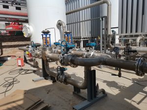
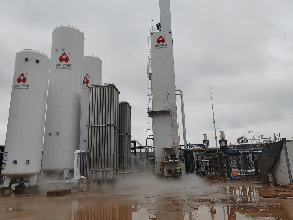
- Product Collection and Delivery: High-purity oxygen is withdrawn (as liquid or vapor) and delivered as LOX or gaseous O₂. A cryogenic pump raises LOX to pipeline pressure or storage pressure; some oxygen may be vaporized to meet gaseous demand. Nitrogen gas (>99.5% purity) is drawn from the LP column top, warmed, and compressed to pipeline or storage pressure. Excess liquid nitrogen (~10% of N₂ output) is often stored as LN₂ for peak shaving. All product streams are warmed by returning them through the cold box, which completes the refrigeration loop.
Each of these steps is precisely controlled and optimized. The Cryogenic Air Separation Process Explained for Industrial Oxygen and Nitrogen Production depends on maintaining strict temperature profiles and pressure levels in the columns. For example, the reflux ratios in each column are adjusted to achieve the target purities: higher reflux yields higher purity oxygen, while leaving some nitrogen in the bottom helps push more oxygen upward. Tight control of column temperatures (via adjusters on trays and control valves) is critical for high recovery efficiency.
Technical Specifications and Data
Cryogenic air separation units (ASUs) are engineered for specific production capacities and product purities. A large cryogenic ASU might produce anywhere from hundreds to thousands of tons of O₂ per day (for example, 1,000 tons/day ≈ 700,000 Nm³/h of O₂) along with about 4–5 times that volume of N₂ (by air composition). Typical product specifications include:
- Oxygen Product: Oxygen purity from a cryogenic ASU is typically 95–99.6% (liquid oxygen), up to 99.9% for specialty grades. Oxygen can be delivered as LOX (liquid) or compressed gaseous O₂.
- Nitrogen Product: Nitrogen purity is usually 99.5–99.99% for bulk N₂ gas. Ultra-high purity (≥99.999%) is possible if required for sensitive applications. Nitrogen is delivered as a gas; some portion (roughly 10%) is often liquefied (LN₂) for storage and peak demand.
- Argon Product (if any): Argon purity is typically ~99.9%. The argon flow is much smaller (argon is ~1% of air by volume).
Other operating parameters include:
- High-Pressure Column: Typically ~5–8 bar.
- Low-Pressure Column: Near ambient (1–2 bar).
- Cold-Box Outlet Temperature: ~–180 to –190 °C.
- Feed Air Requirements: Air must be filtered to sub-micron and dried to very low dewpoints (usually <–70 °C dewpoint).
The table below summarizes representative values:
| Parameter | Value/Range |
|---|---|
| Oxygen purity (product LOX) | 95–99.6% (liquid O₂, up to 99.9%) |
| Nitrogen purity (product gas) | 99.5–99.99% |
| Argon purity (if produced) | ~99.9% |
| Column pressure (HP/LP) | ~5–8 bar / ~1–2 bar |
| Cold-box outlet temperature | –180 to –190 °C |
| Specific power (O₂ production) | ~150–300 kWh per ton O₂ |
| Specific power (N₂ production) | ~0.3–0.5 kWh per Nm³ N₂ |
The specific energy consumption depends on plant size and design. For example, a large modern ASU might use on the order of 150–200 kWh of electricity per ton of O₂ produced. Smaller or older plants may consume up to 300 kWh/t. In terms of nitrogen, this corresponds roughly to 0.3–0.4 kWh per normal m³ of N₂ (since 1 ton O₂ ≈ 700 Nm³ O₂, and 1 ton N₂ ≈ 1000 Nm³ N₂). Efficiency is maximized by advanced heat integration and multi-stage expansion, but cryogenic separation remains energy-intensive by nature.
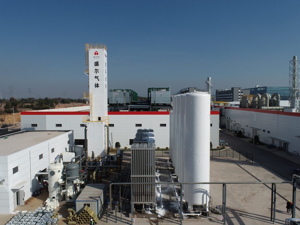
These operating conditions and performance metrics are representative of large-scale ASUs. For example, a high-capacity ASU might deliver 1,000 tons/day of O₂ (≈700,000 Nm³) and correspondingly ~4,000 tons/day of N₂, with oxygen purities >99%. Maintaining the columns and heat exchangers at design pressures yields stable production. Any feed or load fluctuations are often buffered by liquid storage: for instance, having several tons of LOX stored allows the plant to meet short-term demand surges without extra power.
Below is a concise summary of key product delivery specs:
| Product | Purity (%) | Typical Delivery Pressure | State |
|---|---|---|---|
| Oxygen | 95–99.6 (up to 99.9) | ~6–20 bar (LOX pumped up to 200+ bar) | Liquid/Gas |
| Nitrogen | 99.5–99.99 | ~4–6 bar (pipeline) | Gas (or LN₂) |
| Argon | ~99.9 | ~5 bar (if recovered) | Liquid |
In modern plants, the process runs continuously (90–99% uptime) to optimize efficiency. Purity analyzers and inline monitors ensure that O₂ and N₂ meet specifications (often ±0.1%). Table-pressure letdown (via valves or vaporizer systems) converts stored LOX or LN₂ back to gas on demand. All these controls form part of the cryogenic plant’s automation.
Energy Consumption and Efficiency
Despite its separation efficiency, the Cryogenic Air Separation Process Explained for Industrial Oxygen and Nitrogen Production is inherently energy-intensive. Large multi-stage compressors and refrigeration demand mean ASUs consume significant power. A useful rule of thumb is that the process consumes roughly 200–300 kWh of electricity per ton of O₂ produced. (This is several times the theoretical minimum work, because of real irreversibilities and losses.) In terms of N₂, this is roughly 0.3–0.5 kWh per Nm³ of N₂ (since roughly 1 ton O₂ yields ~700 Nm³ O₂ and 1 ton N₂ yields ~1000 Nm³).
Energy use varies with design. Larger plants typically hit the lower end of 150 kWh/t O₂ by leveraging scale and advanced heat integration. Smaller or less-optimized plants may be on the order of 250–300 kWh/t. Key factors include:
- Column Pressure: Lower operating pressure (e.g. 4 bar HP column instead of 6 bar) reduces refrigeration load but requires larger column volume. Designers balance size vs. power cost.
- Heat Exchanger Effectiveness: High-efficiency plate-fin exchangers recover more refrigeration. Better heat integration (more product counter-flow) lowers power draw.
- Expander Use: More expansion stages (turbo-expanders or JT valves) provide additional cooling without extra work input. Often an expander drives a booster compressor on the oxygen side to recycle work.
- Pumping vs. Gas Compression: Pumping LOX to high pressure (for delivery) uses less power than compressing cold gas to the same pressure. Using liquid pumps for oxygen (instead of a big vapor compressor) can save up to ~30 kWh/t.
Because electricity cost is a major operating expense, plants typically run continuously at full load. Some modern ASUs include thermal energy storage (coolant tanks or stored cryogens) to absorb fluctuations. In integrated energy projects (like hydrogen from natural gas), the ASU may coordinate with other units, but historically ASUs are designed for steady base-load operation.
Industrial and Energy Sector Applications
Cryogenic air separation is critical to many industries. For example, the Cryogenic Air Separation Process Explained for Industrial Oxygen and Nitrogen Production provides the pure oxygen and nitrogen needed for key energy processes. Key applications include:
- Hydrogen and Ammonia Production: The cryogenic ASU supplies large volumes of O₂ to steam methane reformers (for blue hydrogen) and gasifiers, while also providing high-purity N₂ as feed for the Haber–Bosch ammonia plant. This integration enables higher furnace efficiency and removes nitrogen dilution. The pure N₂ from the ASU (often ≥99.99%) directly becomes ammonia synthesis feed.
- Synthetic Fuels and Gasification: Processes like Fischer–Tropsch diesel synthesis and biomass/coal gasification rely on oxygen-blown reactors. Cryogenic ASUs deliver the high-purity O₂ required for controlled partial oxidation of feedstock. By supplying oxygen on demand, these plants can run with higher throughput and produce low-carbon synthetic fuels or syngas more efficiently.
- LNG Liquefaction and Cooling: Liquefaction trains often use nitrogen refrigeration cycles (Brayton or Nitrogen-expander). Cryogenic ASUs can produce large volumes of liquid nitrogen for these loops. Stored LN₂ is also used as an inert blanket during LNG ship loading. A portion of the cold N₂ output can even augment the main cold box refrigerant. In some facilities, waste cold nitrogen from the ASU is directly used to pre-cool natural gas.
- Metals and Power Industries: Oxygen-fuel burners and oxy-blast furnaces in steel mills use pure O₂ for higher temperatures and improved efficiency. Cryogenic O₂ enhances electric arc furnaces and waste-to-energy plants. Nitrogen from ASUs is used broadly as an inert purge gas, blanketing agent, and cooling fluid in petrochemical and power plants. The availability of cryogenic N₂ allows safe handling of reactive streams and reduces fire/explosion risks.
- Environmental Controls: Nitrogen is used for emission control (e.g. in selective non-catalytic reduction for NOₓ abatement) and industrial site inerting. For example, ASU-produced N₂ is injected in power plants to suppress combustion temperature or in gas pipelines to purge fluids. In these cases, the Cryogenic Air Separation Process Explained for Industrial Oxygen and Nitrogen Production underpins operations that require ultra-high gas purity for environmental compliance.
In summary, the global trend is toward larger, more efficient ASUs at major energy and industrial sites. Many green or blue hydrogen projects, for instance, include on-site ASUs. Regions with extensive LNG or steelmaking infrastructure rely heavily on cryogenic gas supply. Advanced fuels projects (e.g. synthetic e-fuel plants) often co-locate ASUs. Thus, cryogenic air separation remains fundamental to the energy transition.
Global Perspective and Trends
For decades, the Cryogenic Air Separation Process Explained for Industrial Oxygen and Nitrogen Production has been a cornerstone of global gas supply, even as the technology evolves. Market growth is driven by emerging energy projects: major investments in hydrogen (green/blue), carbon utilization, and LNG capacity all boost demand for O₂ and N₂. Leading gas companies have built thousands of ASUs worldwide.
In regions rich in natural gas (Middle East, Australia) or steel production (Asia, Europe, Americas), cryogenic plants are ubiquitous. Environmental regulations (like carbon capture or oxy-combustion) increasingly rely on pure oxygen, supporting new ASU projects. Researchers are also improving ASU designs: for example, heat-integrated distillation columns (HIDiC) and advanced coolers aim to cut power use. Some innovative plants incorporate thermal storage (warm/cold tanks) to run flexibly with renewables. Membrane and adsorption units are sometimes used as pre-treatment to lighten the cryogenic load. However, for very high purity and large volume, cryogenic distillation remains the preferred solution.
Conclusion
The Cryogenic Air Separation Process Explained for Industrial Oxygen and Nitrogen Production is a cornerstone of modern industry. By leveraging low-temperature distillation, cryogenic ASUs reliably supply ultra-pure oxygen, nitrogen, and argon at the scales needed by heavy industry and energy systems. While energy-intensive, these units enable critical processes such as hydrogen production, advanced fuel synthesis, and LNG processing with unmatched purity and efficiency. Technical optimizations—advanced compressors, heat exchangers, and controls—continue to improve ASU performance. For researchers and engineers, understanding the Cryogenic Air Separation Process Explained for Industrial Oxygen and Nitrogen Production in detail is essential for innovation in the energy transition and related sectors.