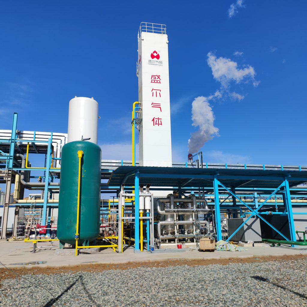
Cryogenic air separation units (ASUs) are the industrial workhorses for producing high-purity oxygen, nitrogen, and argon by distilling air at very low temperatures. These large-scale plants (>100 tons/day O₂) exploit the different boiling points of air components; they are used when very high product purity (>99.5% for O₂) or pressure is requiredispatguru.comispatguru.com. The overall ASU process flow involves several stages: ambient air intake and filtration, multistage compression (with intercooling), removal of moisture/CO₂ (purification), deep pre-cooling, main cryogenic heat exchange, distillation in high- and low-pressure columns, optional argon recovery, and final product handling. This step-by-step guide explains each stage with technical detail and cites current industry practices.
Air Intake and Filtration
Ambient air is drawn through dedicated intakes positioned to avoid contamination (usually elevated or upwind of dust, combustion sources, etc.)asiaiga.org. In practice, ASU intake systems use coarse and fine filters in series: for example, cyclonic or mesh pre-filters plus cartridge filtersasiaiga.org. Screens or demisters prevent insects and rainwater from entering. Differential-pressure gauges on the filters signal when maintenance is needed. International guidelines call for two-stage filtration, including insect screens, rain/snow hoods, and freeze-prevention, to protect the oil-free compressorasiaiga.org. In critical installations, intake air is also monitored (e.g. hydrocarbons analyzer); some automated systems will shut down the ASU if contamination is detected above safe levelsasiaiga.org.
Air Compression and Cooling
Filtered air enters the Main Air Compressor (MAC), typically a multistage oil-free centrifugal unit. Air is compressed to the required distillation pressure, usually on the order of 4–10 atm (4–10 bar)eiga.eu. For large ASUs, 3–5 compression stages are common. After each stage, intercoolers (water-cooled heat exchangers) remove much of the heat of compression and condense out moisturecold-facts.orgeiga.eu. These intercoolers reduce the work load on the downstream cryogenic equipment. After the final stage, the hot high-pressure air is further cooled (often to near ambient temperature) in aftercoolerseiga.eu. At this point most liquid water has dropped out. The compressed air flow is carefully controlled (e.g. by inlet guide vanes and recycle valves) to prevent surge. Key point: the compressor is the single largest energy consumer in the ASUcold-facts.orgeiga.eu. Optimizing its efficiency and intercooling is therefore critical for overall plant performance.
Air Purification and Pre-cooling
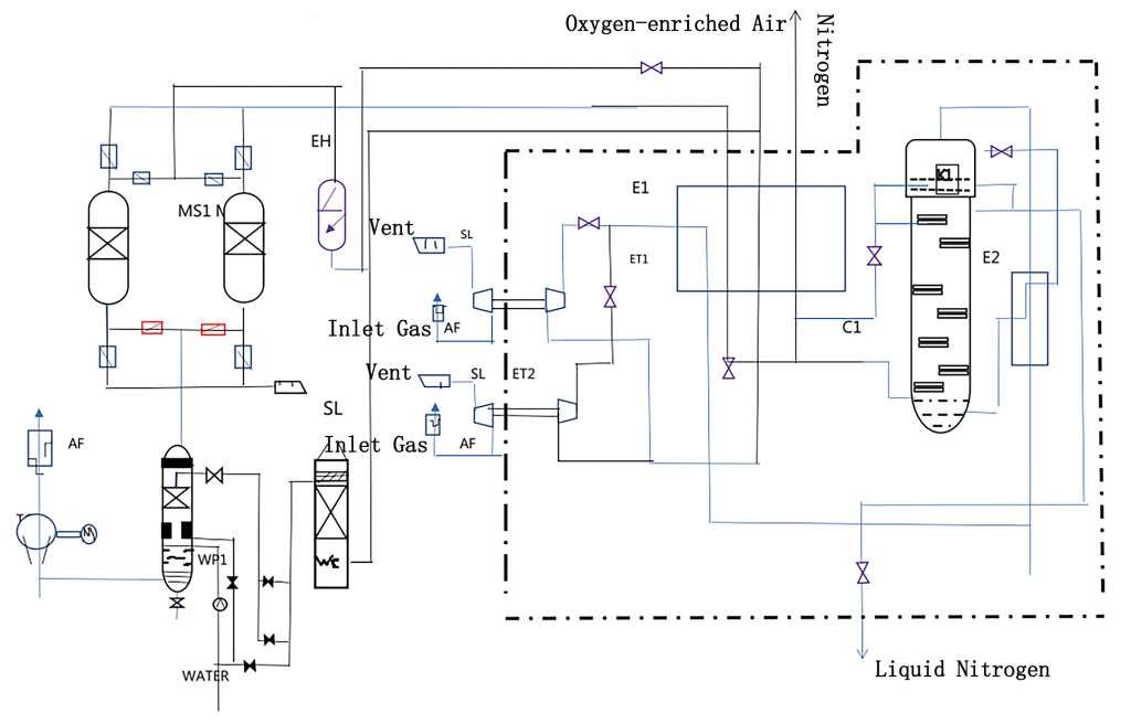
Before deep cooling, the compressed air must be purified of trace condensables (H₂O, CO₂, hydrocarbons) to avoid freezing in the cryogenic exchangers. Two common schemes are used: front-end adsorption or REVEX (reversing heat exchanger). In the adsorption scheme, the hot high-pressure air is sent through beds of molecular sieve and alumina which remove water and CO₂cold-facts.org. These beds alternate between adsorption and regeneration (with dry N₂ purge) so that one line cleans air while another is being regenerated. The result is Clean Dry Air (CDA) at full pressurecold-facts.org. Alternatively, REVEX uses the cryogenic heat exchangers themselves for purification by switching wet and dry passagescold-facts.org. Either way, the goal is to enter the cold box with oil-free, bone-dry, CO₂-free air.
After purification, the air is pre-cooled further against water or an external refrigerant if used, and is finally ready to enter the main cryogenic exchanger. In most modern ASUs, however, this final cooling is done entirely in the cold box against the exiting product streams (see below). By the end of this pre-cooling stage, the air is still gaseous but has given up heat to both intercoolers and purification units, maximizing enthalpy recovery.
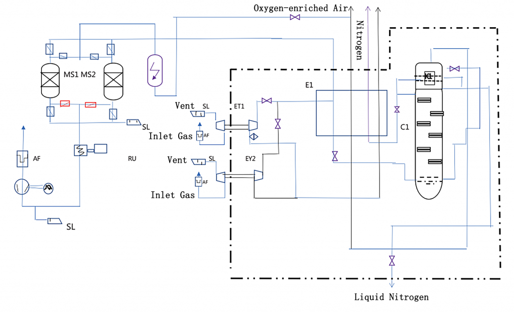
Main Cryogenic Heat Exchanger (“Cold Box”)
The purified high-pressure air is routed into the cold box, a well-insulated enclosure containing all the cryogenic equipment. Here it first passes through the main heat exchanger, a multi-stream brazed aluminum unit (often plate-fin type). In these exchangers the incoming air flows counter-current to the cold outgoing product gases (oxygen and nitrogen). Effectively, the air is progressively cooled against the coldest streams in stages. Modern ASUs typically use two sections of heat exchanger (“warm end” and “cold end”) inside one shellcold-facts.org. At the warm end, the compressed air is cooled against the highest-pressure product gases; at the cold end it is cooled to near its liquefaction point by the lowest-temperature streamscold-facts.orgcold-facts.org. After full duty in the main exchanger, the air leaves at roughly –160 °C (close to its boiling point under pressure)cold-facts.org. At this point most of the feed air is a two-phase (liquid-vapor) mixture ready for distillation.
If present, a turbo-expander (expansion turbine) is often incorporated in the cold box to provide additional refrigeration. In a Modified Claude cycle, a portion of the high-pressure air is expanded through a turbine (or expander), generating significant cooling by isentropic expansioncold-facts.org. This extra refrigeration offsets heat leaks and improves efficiency by simultaneously reducing the warm- and cold-end temperature approaches in the exchangercold-facts.org.
High-Pressure and Low-Pressure Distillation Columns
The core separation is done in two distillation columns arranged in series (sometimes called the double-column design). The High-Pressure (HP) column (often ~4–6 bar) receives the cold, partly liquefied air at its bottomcold-facts.org. Inside this column, ascending vapor and descending liquid undergo fractional distillation. The higher-volatility nitrogen preferentially vaporizes and rises, while the descending liquid becomes richer in oxygen and argon. At steady state the HP column top yields almost pure nitrogen gascold-facts.org. This gaseous nitrogen is sent through the reboiler/condenser (the cold-heat exchanger) to condense it, providing reflux for both columns. The liquid collected at the top is returned as reflux. The HP column sump (bottom liquid) is an oxygen- and argon-enriched mixture (roughly 30–40% O₂)cold-facts.org. A portion of this rich liquid is pumped and expanded into the Low-Pressure (LP) column. Often, a lean nitrogen reflux from the HP top is also introduced into the LP column.
The LP column (near 1 bar) receives the feed from the HP column. It performs the final purification. In the LP column, the falling liquid (rich in O₂/Ar) is stripped by rising vapor, yielding nearly pure oxygen at the bottom and a waste nitrogen gas at the topcold-facts.org. The bottom of the LP column is where liquid oxygen (LOX) accumulates. High-purity LOX is withdrawn from the LP bottom; in a “pumped-LOX” design it may be sent out as a liquid product. In a “gas-phase” design, LOX is partially vaporized and sent through the main exchanger to produce high-purity gaseous O₂cold-facts.org. The LP column top produces low-purity nitrogen (typically with a few percent O₂) which is first used to sub-cool reflux streams and then warmed back in the main exchanger. Any residual cold waste N₂ is vented or used for purge/regeneration.
The table below summarizes key specifications of the two columns:
| Parameter | High-Pressure Column (HPC) | Low-Pressure Column (LPC) |
|---|---|---|
| Operating pressure | ~4–6 bar (4–10 atm)eiga.eu | ~1–1.5 bar (atmospheric)jalonzeolite.com |
| Top product | High-purity N₂ gascold-facts.org | Low-purity N₂ gas (waste)cold-facts.org |
| Bottom product | O₂/Ar-enriched liquid (feeds LP)cold-facts.org | High-purity liquid O₂cold-facts.org |
| Argon extraction | No dedicated draw (Ar stays in bottom) | Argon-rich side-draw (to argon column)cold-facts.org |
<div style=”text-align:center”>*Table: Typical HP vs LP column parameters in a cryogenic ASU* (argon ~1% of air; see text and sources)</div>
Argon Recovery
Because argon’s boiling point is close to oxygen’s, many ASUs include an argon recovery unit. A side-stream of argon-rich liquid (about 30% Ar) is drawn from the LP column, roughly mid-column, where argon has concentrated during the distillationcold-facts.org. This crude argon stream is fed to a separate, specialized distillation column to produce high-purity argon. In modern ASUs, this argon column is often placed adjacent to the LP column and integrated into the cold box. The recovered argon may be exported as a liquid or gas product. (If no argon recovery is needed, the mid-LP liquid simply continues through the main LP separation.) Guidelines note that if argon is to be recovered, its side-draw must be cleanly taken from the appropriate column tray and processed to avoid product contaminationeiga.eucold-facts.org.
Product Extraction and Storage
The final products – oxygen, nitrogen, and argon – leave the cryogenic section as either cold gases or liquids. Typically, the pure gases are warmed back to ambient temperature by passing them counter-current through the main heat exchanger (recovering refrigeration)eiga.eu. Gas products (GOX, GAN) are then sent to client systems or further compression if high pressure is needed. Liquid products (LOX, LIN, LAR) may be stored in cryogenic tanks or pumped for pipeline delivery. Modern ASUs can be configured to produce liquid vs. gas outputs as needed; generating large quantities of liquid O₂/N₂ requires extra refrigeration (often via a nitrogen-expansion liquefier unit)eiga.eu. For example, a typical ASU might deliver LOX to storage and simultaneously warm and compress GOX. It is common to bleed off a small LOX purge from the column bottom to continuously remove any impurities (e.g. hydrocarbons) and avoid accumulationcold-facts.org. In all cases, liquid products are handled in insulated tanks, while gas products may be stored at moderate pressure or sent through pipelines.
A key operational point is that energy consumption rises sharply with desired purity. Published data indicate cryogenic plants generally consume on the order of 200–400 kWh per tonne of O₂ producedtewincryo.com; figures as low as 150 kWh/t (for ~90% purity) and up to 800 kWh/t (for ultra-high purity) are citedthundersaidenergy.com. Table 1 illustrates this trend for illustrative oxygen purities. In practice, the main heat exchanger approach temperatures and column pressure levels are tuned to optimize efficiency for each product specification. Minimizing temperature differences in the exchanger (good thermal integration) is a key design goal for reducing compressor loadcold-facts.orgispatguru.com.
| O₂ Purity (vol%) | Energy (kWh per tonne O₂) |
|---|---|
| ~90% | ~150–200 |
| ~95% | ~200–300 |
| ~99% | ~300–400 |
| ~99.5% | ~350–450 |
<div style=”text-align:center”>*Table: Illustrative oxygen production power vs. O₂ purity. Higher purity demands more energy:contentReference[oaicite:43]{index=43}:contentReference[oaicite:44]{index=44}.*</div>
Safety Considerations
Cryogenic ASUs operate under conditions that require stringent safety measures. Oxygen hazard: Concentrated O₂ supports combustion, so all materials and lubricants in oxygen service must be compatible (metals cleaned of oils, etc.) and meet design standardsasiaiga.org. Compressors, valves, and piping in the air circuit are specially protected or purged for oxygen service. Contamination risk: Any moisture or hydrocarbons in the process air can freeze or react. In particular, water trapped in aluminum packing can generate hydrogen (by Al/H₂O reaction), creating an explosive mixtureeiga.eu. Therefore, ASUs emphasize 100% CO₂/H₂O removaleiga.eu and hydrocarbon monitoring. Pressure relief: All cold vessels and columns have pressure relief devices (PRDs) to guard against blocked-flow or vacuum conditions. Separate expansion tanks and burst discs are also common. Cryogenic hazards: Extreme cold poses burn and asphyxiation risks. Oxygen-enriched atmospheres can develop in enclosed areas. As one safety source notes, “Cryogenic temperatures, nitrogen and oxygen present safety hazards. Additionally, process air contamination from oil and hydrocarbons can combust spontaneously with oxygen.” ASUs therefore include hydrocarbon detectors, oxygen analyzers, and velocity controls, and enforce strict inerting/purging procedurescold-facts.org. For example, operators continuously purge the LP oxygen sump with a small LOX bleed to avoid hydrocarbon buildup (and explosion)cold-facts.org. Monitoring and shutdown: Modern plants have real-time sensors for O₂/N₂ levels and trace contaminants. Control logic can automatically shut down the ASU if dangerous conditions (high hydrocarbon or O₂ levels) are detectedasiaiga.orgcold-facts.org.
Overall, safe ASU operation hinges on rigorous monitoring, quality maintenance of adsorbers and heat exchangers, and compliance with cryogenic plant codes. Operators follow guidelines (e.g. EIGA/CGA recommendations) for equipment materials, insulation, emergency relief, and lock-out/tag-out procedures.
Cryogenic air separation is a complex, highly engineered process. Each step – from intake air preparation through distillation and final product handling – must be precisely controlled to achieve the desired gas purities and production rates while minimizing energy use. By following best practices and industry guidelines (e.g. for filtration, purification, and equipment design) an ASU can run reliably for years, typically delivering oxygen, nitrogen, and argon products at the specified purity and pressure. The combination of efficient heat integration and careful safety design makes the cryogenic ASU a cornerstone technology for modern chemical, metallurgical, and medical gas production.


