Cryogenic Air Separation for Nitrogen is the most reliable technology for producing ultra-high purity nitrogen at industrial scale. By exploiting the different boiling points of nitrogen (−196 °C) and oxygen (−183 °C), fractional distillation in a cryogenic air separation unit (ASU) yields pure nitrogen and oxygen. The cryogenic route dominates when large volumes (hundreds to thousands of Nm³/h) and very high purity (>99.99%) nitrogen are required. This article examines how cryogenic nitrogen generation works, its thermodynamic efficiency, system design elements, and control strategies. Key industrial applications are highlighted (electronics manufacturing, chemical processing, food preservation, etc.), and a comparison to alternative methods (PSA, membranes) is provided. Recent research and patents are also noted to show how the technology is evolving.
Working Principles of Cryogenic Air Separation for Nitrogen Production
Cryogenic separation relies on cooling air below oxygen’s boiling point so that gases can be separated by phase changes. The main steps are:
- Air Compression and Purification: Ambient air is first compressed (typically to 4–7 bar) and moisture/CO₂ are removed using molecular sieve dryers. Clean dry air prevents ice/frost in the cold box.
- Cryogenic Heat Exchange: The purified air passes through high-efficiency heat exchangers (often plate-fin multi-stream exchangers) where it is progressively cooled by heat exchange with outgoing product streams (cold nitrogen and oxygen vapor).
- Air Liquefaction: A portion of the air is expanded through a turbine expander or Joule-Thomson valve, dropping its temperature further and partially liquefying the air. This counter-flow of cold and warm streams maximizes the low temperature.
- Fractional Distillation Columns: The liquefied air enters one or more distillation columns (usually a high-pressure (HP) column feeding a low-pressure (LP) column). In the columns, oxygen and nitrogen separate by their boiling points. Oxygen (more volatile) boils off at the top of the column, while liquid nitrogen collects at the bottom. Typical cryogenic units use double-column arrangements: the HP column reboils with aid of a column condenser, and its bottom liquid (oxygen-rich) feeds the LP column. In the LP column, the bottom liquid is very pure LOX (liquid oxygen) and the top vapor is almost pure nitrogen.
- Product Extraction and Reflux: High-purity nitrogen (often >99.99%) is withdrawn from the top of the LP column as gas or can be condensed and stored as liquid. Some nitrogen vapor is also used as reflux or refrigeration by re-expanding it back into the heat exchanger. Any residual oxygen product is taken from the LP column bottom or the HP column.
Each of these steps must be carefully balanced. The cryogenic cascade of compressors, heat exchangers, expanders, and columns is designed so that the cold energy is fully utilized. The process runs continuously, producing a steady flow of nitrogen and oxygen (and optionally argon). In practice, a modern ASU is a multi-stream counterflow system with integrated compressors and expanders in a cold box.
Key aspects of the working principle include:
- Fractional Distillation: Separation based on boiling point differences, with nitrogen boiling off before oxygen.
- Heat Integration: Multiple heat-exchanger stages ensure the cold from expanding gas is used to chill incoming air.
- Refrigeration Cycle: Turbine expanders (Joule-Thomson or turboexpanders) provide the necessary cooling to reach liquefaction.
- Pressure Levels: Two pressure levels (HP and LP) allow efficient reflux without excessive compression work.
Overall, cryogenic air separation for nitrogen uses well-established thermodynamic cycles (the Claude or Linde cycle) to achieve high purity. The design can be represented schematically, but key equipment and operating steps are:
- Compress air → Remove impurities → Pre-cool against product streams → Expand to liquefy → Separate in columns → Reheat and recover N₂/ O₂ → Provide reflux.
Thermodynamics and Energy Efficiency
Cryogenic air separation units are among the most energy-intensive processes in the industrial gas industry. The main reason is the large refrigeration duty needed to liquefy air. From a thermodynamic viewpoint, separating nitrogen requires input work (power) to overcome both the heating/compression and the low-temperature cooling requirements. The minimum theoretical work (Carnot limit) is set by the thermodynamic properties of air, but real ASUs have many irreversibilities.
In practice, specific energy consumption for a cryogenic nitrogen plant depends on product purity, pressure, and recovery. Typical values are on the order of 0.4–0.7 kWh per Nm³ of N₂ gas produced (at standard conditions) when producing liquid nitrogen. In more familiar terms, industry data indicate roughly 550 kWh per tonne of liquid N₂ (≈0.55 kWh/kg) is needed for conventional distillation. For comparison, small PSA systems might use 300–600 kWh/tonne N₂, and membranes even lower at higher purities. For ultra-pure (99.999%) nitrogen, energy use rises further.
Several factors affect the energy efficiency:
- Second-Law (Exergy) Efficiency: Most ASUs operate far below thermodynamic optimum. Exergy analyses show that only a small fraction (often <10–15%) of the ideal work is achieved in real systems due to irreversible expansion, heat transfer losses, and inefficiencies in compressors/expanders. For example, a recent exergy study found actual PSA generators had 5.5–11.2% second-law efficiency, indicating room for improvement. Cryogenic ASUs typically do slightly better but still suffer large exergy destruction in multi-stage expansion and heat exchange.
- Recovery vs Purity: The more nitrogen is recovered (or the higher the purity), the more work is required. Thermodynamically, raising purity from 98% to 99.999% significantly increases the required refrigeration and compression duty. High recovery (approaching 100% of N₂ in feed) also demands more energy.
- Refrigeration Strategy: Use of turboexpanders (isothermal-like expansion) versus simple Joule-Thomson valves (isentropic throttling) influences efficiency. Turboexpanders recover work from expansion and produce colder gas, improving efficiency. Multi-stage expander trains and use of expansion in multiple streams can significantly lower energy use compared to single-stage expansion.
- Heat Exchanger Effectiveness: Heat exchanger performance (approach temperature) is critical. High-efficiency plate-fin exchangers allow smaller temperature differences and lower irreversibility. Any temperature cross-over or large ΔT penalties increase required work.
- Integration and Cycle Innovations: Recent research proposes hybrid cycles and heat integration to reduce power. For example, Low-Energy, Low-Cost ASU (LEC-ASU) designs integrate a heat pump and thermal storage with the cryogenic cycle to partially recycle cold. Integrating liquefied natural gas (LNG) cold energy or using low-grade waste heat are also studied ways to boost efficiency. Some studies model combined cycles (chemical looping, absorption heat pumps, etc.) to cut energy by over 10%.
Despite high power consumption, cryogenic ASUs are often more efficient than alternatives at very large scale due to economies of scale. For production of thousands of Nm³/h, the specific power of a cryogenic plant can be comparable to or even lower than small PSA systems at lower throughput. Industry benchmarks (EIGA reports) indicate modern large ASUs may use ~500–600 kWh/tonne N₂ (liquid basis), whereas medium PSA might use 300–1000 kWh/tonne (depending on purity), and membranes often slightly less but at lower purity.
In summary, cryogenic N₂ separation requires substantial refrigeration work, but sophisticated multi-stage cycles and integration strategies are continuously improving the efficiency. Key goals are to minimize temperature differences, recover expansion work, and optimize reflux to approach the thermodynamic minimum work as closely as practical.
Equipment and System Design
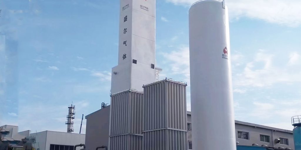
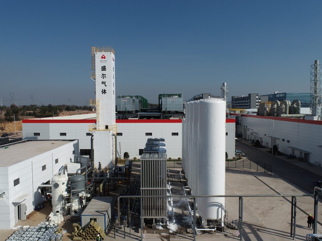
A cryogenic nitrogen plant consists of several major pieces of equipment, each contributing to overall performance. A typical plant is modularized and can be skid-mounted for smaller units or field-erected for large plants. Key components include:
- Air Compressor(s): Multi-stage, oil-lubricated or oil-free screw or centrifugal compressors boost ambient air to the process pressure (often 5–7 bar). Large ASUs may use two compressor trains. Intercoolers between stages remove heat to reduce work.
- Pre-treatment Skid: Downstream of compression, air passes through a refrigeration dryer and molecular sieve beds (typically dual adsorbent towers) to remove water, CO₂, hydrocarbons. This is critical to prevent freeze-out in the cold box.
- Cryogenic Heat Exchangers (Cold Box): The heart of the system is the cold box. Multiple plate-fin or brazed aluminum heat exchangers interlink the flows of warm compressed air with cold product gases. Plate-fin units are common for high efficiency and compactness. In the cold box, heat exchangers perform feed precooling, inter-stage cooling, and reheat of nitrogen and oxygen.
- Expansion Devices: Typically a turboexpander (cryogenic expander-generator) or expansion valve provides the refrigeration. Turboexpanders (driven by air pressure drop) are preferred in larger plants because they extract work and produce cold high-flow gas; small plants may use expansion valves (J-T valves) for simplicity. Some systems employ more than one expander stage.
- Distillation Columns: Most ASUs use a high-pressure column (around 5–6 bar) whose bottom liquid feeds a low-pressure column (around 1–1.5 bar). The columns can be tray-type or packed. The HP column condenses some top vapor via the LP column reboiler. The LP column bottom provides liquid oxygen, top vapor provides gaseous nitrogen. Valves and pumps route flows between columns.
- Auxiliary Systems: Pumps are used if liquid oxygen or nitrogen is to be distributed or for pumping liquid streams back to columns. Vaporisers heat stored liquid products to gas for delivery. Cold vaporisers and storage tanks are included if liquid products are supplied.
- Control and Sensors: The system includes O₂/N₂ analyzers, pressure/temperature sensors, and control valves. A control system (DCS or PLC) manages compressor speeds, reflux ratios, and safety interlocks. Purge valves relieve pressure and vent waste gases as needed.
Design details can vary. For example, single-column designs exist but are rare for nitrogen-only plants. Often modern plants incorporate energy-saving features: argon-recovery side columns, enriched feed cycles, or pumped reflux. Manufacturers also use high-efficiency compressor motors, sophisticated bearing systems in expanders, and automated startup sequences.
Key design considerations include:
- Scale and capacity: Cryogenic plants are suited to large flows. A small-scale plant (e.g. <100 Nm³/h of N₂) is uncommon; typical cryogenic nitrogen units produce several hundred to >10,000 Nm³/h. Capital cost per unit N₂ output decreases with scale.
- Purity requirements: Ultra-high purity (UHP) nitrogen (>99.999%) may require extra adsorbers and reflux, and slightly higher power. Designs must allow tuning of O₂ removal (down to ppm levels).
- Flexibility: Some plants are designed to vary N₂ vs O₂ output. For instance, chemical plants may want more O₂ at times, so the column split can be adjusted. Integrated sensors and controls support flexible production.
- Safety features: Cryogenic equipment has inherent hazards (extreme cold, pressure). Designs include pressure relief devices, low-temperature alarms, and emergency shutdown logic. Materials (stainless steel, aluminum alloys) must handle low temperatures without brittleness.
An illustrative list of typical ASU equipment is:
- Screw/centrifugal air compressor(s) with aftercoolers
- Refrigerated air dryer and molecular sieve adsorbers (CO₂/H₂O removal)
- Feed air intercooler/coolers
- Main heat exchanger (cold box with multi-stream plate-fin exchangers)
- Turboexpander(s) or expansion valve(s) (for refrigeration)
- High-pressure distillation column (with internal trays or packing)
- Low-pressure distillation column (with reboiler)
- Pumps for liquid O₂/N₂, vaporisers
- Instrumentation (O₂ analyzers, sensors, control valves)
Design innovations may include compact heat exchangers, advanced sealing in expanders, and integrated expanders with motors. Some recent patents describe dual-expander configurations or “pipe-in-pipe” exchangers. Overall, the system design seeks to maximize energy recovery and ensure reliable delivery of the required nitrogen grade and flow.
Control Considerations
Managing a cryogenic nitrogen plant requires careful control of flows, pressures, temperatures, and purity. Key control objectives include:
- Product Purity Control: The O₂ content in the nitrogen product is regulated by adjusting reflux (liquid return) and boilup rates in the columns. For example, if O₂ analyzer shows rising O₂ in N₂, control valves divert more liquid nitrogen back into the column as reflux, stripping out O₂. Secondary controls may adjust feed air flow or column bottom draw. Maintaining constant purity under varying load is a dynamic challenge.
- Flow and Pressure Control: Compressed air flow into the ASU is matched to demand. If less N₂ is needed, part of the feed air can be purged or the compressor speed reduced. Column pressures are controlled via adjustable pressure valves and recycle flows. The pressure balance between the HP and LP columns is critical; for instance, condensers in the HP column must maintain a set reflux pressure.
- Level Control: Liquid levels in the column bottoms and reboilers are kept at setpoints using level transmitters and automatic control valves. This ensures enough liquid for fractionation without flooding. Instrumentation measures cryogenic liquid levels (often capacitance or radar gauges) to control pumps and reflux flows.
- Temperature Control: Temperatures at various points (exchanger outlets, expanders) indicate performance. Temperature sensors help fine-tune heat exchanger bypass and ensure efficient refrigeration.
- Start-up and Shutdown Sequencing: Due to the risk of oxygen freezing or excessive pressure, start-up follows a precise procedure: gradual cooling of the cold box, slow compressor ramp-up, and controlled introduction of expansion cooling. Automated sequences prevent operator error. Likewise, controlled shutdown avoids thermal shocks by warming the plant with recirculated hot gas.
- Safety Interlocks: Overpressure protection (relief valves), oxygen monitors (prevent explosive mixtures), and alarms for low temperature or flow are integral. The control system must also handle emergency scenarios, such as diverting the product to flare and safely depressurizing the unit if a fault occurs.
Advanced control strategies (model-predictive control, cascade loops) can improve performance. For example, coordinating all loops (compressor speed, column reflux, heat exchanger bypass) can minimize off-spec production and power swings. However, cryogenic plants are relatively slow-responding (due to thermal inertia), so controllers emphasize stability over quick maneuvering.
In summary, control of a cryogenic nitrogen ASU focuses on keeping the separation process steady and safe. Key control points are product purity (monitored by analyzers), pressures in each column, and proper refrigerant balance. With modern digital controllers, the unit can automatically adjust to meet changing N₂ demand while maintaining set purity and efficiency.
Industrial Applications and Recent Advances
Cryogenic nitrogen plants are used wherever very pure or large-volume nitrogen is needed. Key applications include:
- Electronics Manufacturing: Semiconductor and PCB fabrication require ultra-pure N₂ for wafer processing, chemical vapor deposition, and as a nitrogen purge gas. Any oxygen or moisture can ruin sensitive processes. Large fabs often have on-site cryogenic N₂ to supply hundreds of liters/minute at 99.999% purity.
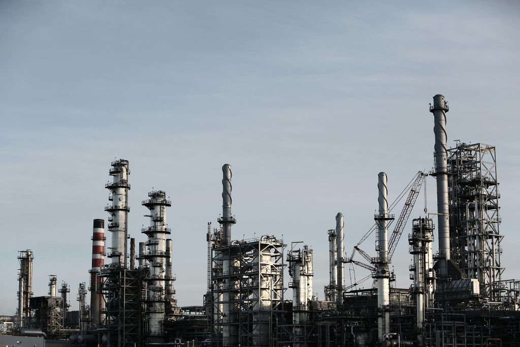
- Chemical Processing: Many chemical reactions and storage operations use nitrogen blanketing or pressure inerting (e.g. storing gasoline or chemicals without explosion risk). Cryogenic N₂ ensures a pure, dry, inert atmosphere. Large-scale ammonia plants and refineries use N₂ in prilling towers or catalysts.
- Food Preservation: Modified atmosphere packaging (MAP) displaces oxygen with nitrogen to extend shelf life of packaged foods. Cryogenic liquid or gas nitrogen is used in freezing tunnels or in cryogenic freezing of fruits, vegetables, and meats (freezing or chilling pipelines with liquid N₂).
- Metallurgy and Metal Fabrication: Nitrogen is used in annealing, heat treating, and laser cutting (as an inert shielding gas). Metals like steel may be heat treated in a nitrogen atmosphere to prevent oxidation.
- Aerospace and Defense: Large liquid oxygen plants often co-produce liquid nitrogen. Additionally, nitrogen is used as pressurant in rocket fuel tanks and purges in aerospace systems.
- Medical and Pharmaceutical: Although medical-grade O₂ is the main product, the N₂ co-produced in large cryogenic units can supply hospitals or pharmaceutical plants with high-purity N₂ for inerting or equipment sterilization.
Recent research and developments in cryogenic N₂ generation focus on efficiency and flexibility. For example:
- A 2024 exergy analysis study (Rinker et al.) quantified the minimum work for N₂ separation and found existing systems operate far below ideal efficiency. Such analyses highlight where losses occur (e.g., low-pressure loss, heat transfer gaps) and motivate design improvements.
- Novel cycle designs have been proposed. The Low-Energy Low-Cost ASU (LEC-ASU) concept integrates a heat pump and cold thermal storage with the distillation cycle, reportedly cutting power by 10–15%. Other proposals include blending chemical looping or absorption refrigeration to share the cooling load.
- Renewable integration: Researchers are studying use of solar or wind energy to run ASUs, and even using ASUs for energy storage (Liquid Air Energy Storage, LAES). In those schemes, excess renewable power liquefies air (producing N₂ and O₂), which can later be used to generate electricity or industrial gas.
- Patents and industrial innovation: Cryogenic ASU manufacturers continuously patent enhancements. For instance, patents have been filed for dual-column cycles that re-compress column head vapor to produce high-pressure N₂ or improve reflux. Others cover advanced heat exchanger designs or onboard argon recovery. These innovations aim to boost N₂ recovery, cut power, and reduce plant footprint.
Comparison of Nitrogen Production Technologies
While cryogenic distillation is ideal for large, ultra-pure flows, smaller or portable needs are often met by Pressure Swing Adsorption (PSA) or membrane systems. The table below compares typical values for key parameters: recovery, purity, energy use, and capital cost for the three main technologies.
| Parameter | Cryogenic Distillation | PSA (Pressure Swing Adsorption) | Membrane Separation |
|---|---|---|---|
| Recovery Rate (N₂) | High (≈80–95%) | Moderate (≈60–80%) | Lower (≈50–60%) |
| Nitrogen Purity | Up to 99.999% (UHP possible) | 95–99.999% (often ≤99.5% at high flow) | ~95–99.5% (max ~99%) |
| Energy Consumption | High (~0.4–0.7 kWh/Nm³ N₂) | Moderate (~0.2–0.6 kWh/Nm³ N₂) | Low (~0.1–0.4 kWh/Nm³ N₂) |
| Capital Cost | Very High (multi-MUSD) | Moderate (≈$100k–$1M) | Low (tens–low hundreds kUSD) |
- Recovery Rate: Cryogenic systems can recover most of the N₂ in feed air because nearly all feed ends up as product (except a small purge for cooling). PSA and membrane waste a significant portion of feed air (oxygen-rich off-gas), so recoveries are inherently lower.
- Purity: Cryogenic ASUs achieve the highest purities (suitable for electronics and medical). PSA can also reach very high purity (with multi-bed cycles) but often operates around 99–99.9%. Membranes typically top out around 99% N₂.
- Energy Use: Cryogenic has the highest energy use per unit N₂, as discussed (on the order of 0.5–0.7 kWh/Nm³). PSA units use less power when making moderate purity (especially <99%), rising with purity. Membrane systems are generally most energy-efficient but only up to moderate purity (95–98%). Note: These values vary greatly with operating pressure, feed conditions, and purity demand.
- Capital Cost: Cryogenic plants require expensive cryo-compressors, cold boxes, and infrastructure (often several million USD). PSA units are simpler adsorption skids (hundreds of kUSD to a few MUSD). Membrane systems are simplest and cheapest at small scale (tens of kUSD for small modules).
This comparison shows why cryogenic ASUs are chosen for large-scale, high-purity applications (even though capital and energy costs are high), whereas PSA or membranes suit smaller-scale or lower-purity needs.
Table: Comparison of nitrogen production technologies by key performance metrics. Values are indicative for typical industrial units.
In practice, engineers select the technology by balancing these factors against application needs. For example, the semiconductor industry typically uses cryogenic N₂ due to purity, while a small brewery might use a PSA or membrane N₂ generator for food-grade nitrogen at lower cost.
Final Observation
Cryogenic air separation remains the benchmark method for large-scale, high-purity nitrogen supply. Its working principles are well understood, but continuous improvements in design and control are raising efficiency and flexibility. By carefully integrating refrigeration cycles, compressors, and distillation columns, modern ASUs deliver pure nitrogen reliably. Ongoing research (both academic and industrial) is focused on reducing the high energy and capital costs through novel cycle designs, advanced heat integration, and automation. As industries demand ever-purer nitrogen for electronics, chemical processing, cryogenics, and more, cryogenic air separation systems will continue to evolve, leveraging new materials and controls while maintaining their fundamental operating principles.


