This type of oxygen production unit is now a standard utility asset in steel, chemicals and energy projects, but the way these units are engineered is still often misunderstood. From the outside a cold box looks like a simple insulated tower; inside, a tightly coupled system of compressors, molecular sieve adsorbers, plate-fin heat exchangers, distillation columns and control loops works together to deliver high-purity oxygen at the required pressure, flow rate and reliability. In other words, the cold box is the visible shell of a modern cryogenic air separation oxygen equipment train.
1. Industrial role and design envelope
For most users the first question is not “how does it work?” but “what can it deliver?”. A typical cryogenic air separation oxygen equipment train covers a capacity range from about 1,000 to more than 40,000 Nm³/h of gaseous oxygen, with product purities between 93% and 99.6% by volume. Plant configuration depends strongly on the host process: steel plants often require medium-pressure oxygen for basic oxygen furnaces, gasifiers need stable flows at higher pressure, while glass and non-ferrous applications may combine low-pressure oxygen with liquid back-up.
In this context cryogenic air separation is chosen whenever three conditions come together: large oxygen demand, relatively high purity and long-term continuous operation. Below a few hundred Nm³/h, non-cryogenic technologies are usually more economical; above that threshold, the specific power and lifecycle cost of a well-designed plant become competitive, especially when nitrogen or argon will also be sold.
2. Process structure behind the cold box
The internal structure of cryogenic air separation oxygen equipment can be viewed as a set of tightly integrated building blocks. Although flowsheets vary, most plants share a common backbone:
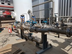
- Feed air compression – Ambient air is filtered and compressed in a multi-stage centrifugal compressor with inter-stage cooling. Discharge pressure typically lies between 5 and 7 bar(g), high enough to drive the downstream process but low enough to limit power consumption.
- Pre-treatment – The compressed air passes through a pair of molecular sieve beds that adsorb water and CO₂. Beds operate in an alternating adsorption-regeneration cycle, so the cryogenic section always sees “dry, CO₂-free” air and the risk of ice or dry-ice formation is removed.
- Main heat exchange – The clean air is cooled close to its dew point in aluminum plate-fin heat exchangers. Cold product and waste streams returning from the columns provide most of the refrigeration, so temperature profiles and minimum approach temperatures must be carefully controlled.
- Expansion and refrigeration – Part of the air, or a nitrogen side stream, is expanded through a turbine to generate additional refrigeration. Turbine inlet conditions and flow rate are key levers when operators balance power consumption, column pressures and product rates.
- Rectification – Inside the high- and low-pressure columns, rising vapour and descending liquid come into contact on trays or structured packing. Over many stages, oxygen-rich liquid collects at the bottom of the low-pressure column, while nitrogen-rich vapour leaves the top. A thermally integrated condenser-reboiler couples the two columns and fixes the operating pressure levels.
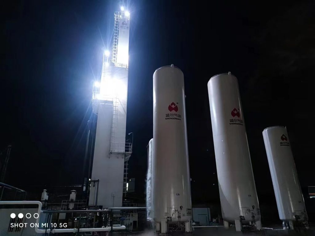
- Product conditioning – Oxygen may be withdrawn as gas directly from the low-pressure column, or as liquid that is then pumped to high pressure and vaporised. The choice between “gaseous only” and “liquid plus gaseous” designs drives both layout and economics for the unit.
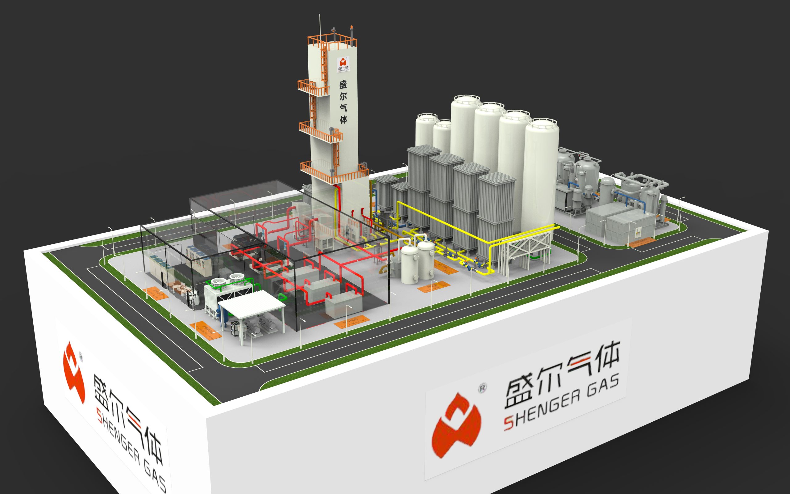
3. Typical equipment configuration
From a mechanical standpoint, cryogenic air separation oxygen equipment is dominated by three subsystems: the main air compressor, the cold box and the oxygen compression or pumping system. An illustrative configuration is shown below.
Table 1 – Example configuration for three plant sizes (indicative)
| Parameter | Small unit | Medium unit | Large unit |
|---|---|---|---|
| O₂ capacity (gaseous, Nm³/h) | 1,000 | 5,000 | 20,000 |
| O₂ purity (vol.%) | 95–99.5 | 95–99.6 | 95–99.6 |
| Main air compressor | 1 × centrifugal | 1 × centrifugal | 2 × centrifugal |
| Air discharge pressure (bar(g)) | 5.5 | 5.5–6.0 | 6.0–6.5 |
| Expansion turbine | 1 radial | 1–2 radial | 2 radial |
| Cold-box column system | Double column | Double column | Double column + argon column (optional) |
| O₂ delivery mode | Gas only | Gas + limited LOX | Gas + LOX back-up |
These numbers are not design rules, but they capture how cryogenic plants scale: as capacity increases, specific power falls, column systems become more sophisticated and liquid back-up becomes standard rather than optional.
4. Performance indicators that matter in practice
When engineers evaluate cryogenic air separation oxygen equipment, they rarely look at a single efficiency number. Instead they work with a small set of practical indicators:
- Specific power, expressed in kWh per Nm³ of oxygen at specified purity and pressure. This figure is the cornerstone of lifecycle cost calculations.
- Net oxygen yield, defined as useful product oxygen divided by oxygen entering with the feed air. Column design, reflux ratio and operating pressure all influence the yield.
- Turndown range, i.e. the ability to reduce oxygen output while staying within purity, stability and mechanical limits. Modern plants often need to follow host-process load changes rather than operating at fixed design rate.
- Plant availability and restart behaviour – Time to reach on-spec product after a cold start and the frequency of interventions on major rotating equipment directly affect the economics of continuous processes such as steel or gasification.
An example set of performance ranges is given in Table 2.
Table 2 – Indicative performance ranges
| KPI | Typical range |
|---|---|
| O₂ purity (vol.%) | 93–99.6 |
| Specific power (kWh/Nm³ O₂) | 0.35–0.65 |
| O₂ delivery pressure (bar(g)) | 2–4 (low-pressure), 15–40 (high-pressure via LOX pumping) |
| Turndown | 60–100% of nameplate |
| Annual availability | > 98% with preventive maintenance |
5. Design choices and trade-offs
Real projects are driven by compromises. Raising oxygen purity improves downstream reaction selectivity or flue-gas CO₂ concentration, but also increases column height, reflux demand and power consumption. Delivering oxygen at high pressure through liquid pumping and vaporisation is usually more efficient than pure gas compression, yet it requires cryogenic storage, additional safety systems and more complex operational procedures within the unit.
Integration with the host site is another powerful lever. In power or synthesis-gas projects, coupling expansion turbines with gas-turbine cycles, or recovering low-grade heat from process units to regenerate molecular sieves, can reduce net power consumption. Conversely, sites with weak electrical infrastructure sometimes accept a less optimised flowsheet in exchange for simpler operation and lower starting current.
6. Practical considerations for engineers and researchers
For engineers specifying new cryogenic air separation oxygen equipment, a clear definition of boundary conditions is more valuable than an idealised process model. Key questions include:
- What oxygen purity and pressure are really required at each consumer, and how much margin is needed?
- How will demand vary over a 24-hour and annual cycle?
- Is there a realistic market for co-product nitrogen or argon, or should the design focus on oxygen only?
- What limits exist on footprint, building height, cooling water and electrical connection?
For researchers, cryogenic air separation remains a rich field. Improvements in packings and trays, better understanding of column hydrodynamics at very low temperature, and more accurate property data all translate into smaller temperature approaches and lower energy demand. On the control side, soft sensors and model-based predictive control make it possible to run closer to constraints, protecting the main heat exchanger from freezing while extracting the last few percent of efficiency from the cryogenic air separation oxygen equipment.
7. Conclusion
Seen from a distance, cryogenic air separation oxygen equipment is just another utility package on a P&ID. Up close it is a finely balanced thermodynamic system whose design reflects dozens of trade-offs between purity, pressure, flexibility and cost. For technical teams responsible for new investments or performance improvements, a good understanding of how the compressor train, cold box and product handling sections interact is essential. With careful integration into the host process and disciplined operation, cryogenic air separation oxygen equipment can supply large volumes of oxygen for decades with high availability and competitive lifecycle economics.