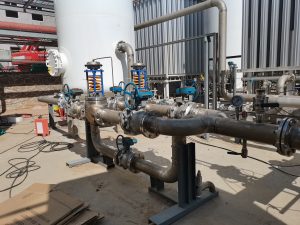
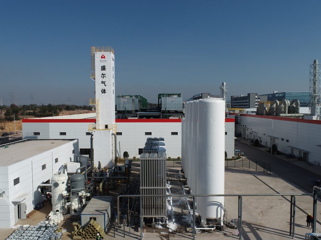
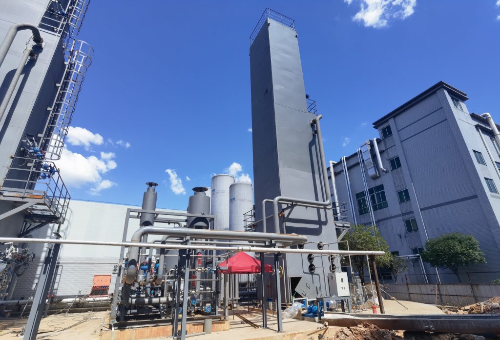
Cryogenic air separation systems compress, purify, and cool ambient air to very low temperatures, then separate it via distillation into high-purity oxygen, nitrogen, and argon. Such systems include compressors, purification beds (molecular sieves), heat exchangers (coldbox), expanders, and tall distillation columns. This requires managing extreme temperature and pressure differences across equipment. Maintaining stable operation of these components is critically important.
Cryogenic air separation systems operate continuously (24/7) to supply industrial gases used in steelmaking, petrochemicals, medical oxygen, and more. Fluctuating demands pose a challenge because ASUs cannot start and stop quickly. In practice, demand swings often require temporary storage or venting of excess gas. For example, one study notes that “continuous ASU operation conflicts with fluctuating end-user demands, frequently resulting in gas overproduction and subsequent venting losses”.
Safety Hazards and Operational Risks in Cryogenic Air Separation Systems
Cryogenic air separation systems (ASUs) pose several unique safety hazards. Four primary risk categories are recognized: rapid oxidation of materials in oxygen service (fire/explosion risk); sudden pressure excursions (from liquid vaporization or blockages); oxygen-rich or oxygen-deficient atmospheres (fire or asphyxiation hazard); and material embrittlement at cryogenic temperatures. Other concerns include moisture or CO₂ freeze-ups in heat exchangers, which can block flow and concentrate contaminants.
Examples of key hazards include:
- Oxygen ignition: Pure oxygen can ignite hydrocarbons, dust, or compressor oil unexpectedly.
- Pressure surges: Blockages or sudden phase changes can overpressure equipment.
- Cold embrittlement: Standard steels become brittle at –196 °C, so ASU vessels use specialized alloys.
- Asphyxiation risk: A nitrogen leak or boil-off gas can displace air and cause oxygen deficiency.
- Freeze/blockage: Trace water or CO₂ can freeze in the coldbox, blocking flow and potentially creating a flammable mixture upon thaw.
Mitigating these hazards relies on conservative design and strict controls. For example, dual isolation (double block-and-bleed) valves allow safe maintenance, and any vented oxygen is routed to safe stacks away from personnel. The coldbox is vacuum-insulated to prevent air ingress, and all low points have drains to flare. Electrical and spark-producing tools are prohibited in oxygen zones, and oxygen-compatible lubricants are used throughout the system.
Design Controls and Mitigation
Safety is engineered into every cryogenic air separation system design. Pressure vessels and piping for cryogenic service are designed under the ASME Boiler & Pressure Vessel Code (Section VIII). These standards require appropriate material toughness and rigorous inspections. The main heat exchanger and columns are built of alloys rated for low-temperature impact, and welded assemblies are tested for leaks. Cold equipment is vacuum-jacketed and insulated to minimize heat leak. Key valves and fittings are rated for oxygen service, and all welds use low-hydrogen procedures to avoid contaminants.
Redundancy and safe isolation are also incorporated. Most large ASUs have parallel compressors or expanders so one unit can remain online while another is serviced. Critical lines (e.g. liquid oxygen feed) use double-block isolations to permit valve repairs without venting. Backup systems like auxiliary cooling or inert purge can keep the plant in a safe standby mode if the main refrigeration train trips.
Instrumentation and control logic provide active protection. A distributed control system (DCS) continuously monitors pressures, temperatures, flows, and gas compositions. Key safety interlocks automatically trip the plant if parameters exceed limits; for instance, the compressor controller shuts down on low suction pressure or overspeed to protect the low-pressure column. Sensors are often duplicated or cross-checked to avoid spurious trips. Safety instrumented functions handle any single-point failures so that the plant defaults to a safe state on major faults. By combining conservative design (per CGA, ISO, and ASME guides) with automated protection, modern cryogenic air separation systems are resilient against common off-normal events.
Operational Stability and Process Control in Cryogenic Air Separation Systems
Stable operation is key to safety and efficiency. Cascade PID controllers and logic solvers regulate column pressures, flows, and reflux ratios to keep the cryogenic distillation towers in balance. Operators aim to minimize upset cycles: instead of frequent startups, ASUs often run at a steady base load, using storage tanks or slip streams to handle short-term demand shifts. Studies have shown that reducing start-stop cycles significantly cuts product losses and avoids emergency venting.
Real-time monitoring supports this stability. Operators watch critical trends such as column bottom temperature, liquid levels, and compressor power. Deviations beyond tight bounds trigger alarms and corrective actions. For example, a gradual rise in the low-pressure column’s bottom temperature might signal a refrigeration imbalance, prompting an adjustment to maintain setpoint. Remote and automated shutdowns are in place: any hazardous signal (e.g. detected high oxygen in an oxygen-bearing line) initiates a rapid safe shutdown sequence. Environmental sensors also inform safety. Oxygen analyzers in machine rooms and analyzer shelters detect leaks early. Cold-box insulation vacuum is monitored so any degradation (air ingress) is caught immediately. Together, these indicators help keep the cryogenic process within controlled limits.
Safety Standards and Best Practices
Industry consensus standards and regulations underpin ASU safety. The CGA P-8/AIGA 056 guideline, for example, provides harmonized safe-practice advice for cryogenic air separation plants, including hazard analysis, plant layout, and operating procedures. ISO 20421-1:2019 specifies design and testing requirements for large cryogenic vessels, and its principles (impact testing, material certification, inspection) are applied to stationary tanks and cold boxes. ASME B31.3 and Section VIII codes cover pressure piping and vessels for cryogenic duty. These standards ensure that equipment selection, fabrication, and testing meet international safety criteria.
In addition, facilities follow internal protocols and regulatory mandates. Permission-to-work, lock-out/tag-out, and hot-work permits are strictly enforced. Processes are audited by HAZOP teams to identify any unnoticed hazards. PPE (cryogenic gloves, face shields) is mandatory when handling cold fluids. Emergency procedures – including specific drills for oxygen or nitrogen releases – are practiced regularly. By aligning with ISO, ASME, and CGA guidelines, and maintaining a strong safety culture, plants achieve reliable and safe operation.
Table: Operational Safety Indicators and Failure Modes
| Failure Mode / Indicator | Cause / Description | Impact / Hazard | Mitigation / Control |
|---|---|---|---|
| Column/Vessel overpressure | Blockage or rapid vaporization | Vessel rupture; cryogenic gas release | Relief valves; double isolation; scheduled inspections |
| Exchanger freeze/blockage | Water/CO₂ freeze in coldbox or HX | Loss of refrigeration; column upset | Air pretreatment; purge flows; periodic warm-up |
| Compressor/expander failure | Mechanical fault or power loss | Sudden loss of cooling; unscheduled shutdown | Redundant units; anti-surge and soft-start logic |
| Oxygen-line leak (high O₂) | Valve seal failure or overpressure | Oxygen-enriched fire atmosphere | O₂ monitors; inert purge/vent; remove ignition sources |
| Control/instrument fault | Sensor drift or PLC error | Incorrect control actions; potential upset | Redundant sensors; fail-safe PLC; frequent calibration |
| Power outage / ESD trigger | Utility failure or emergency shutdown | Plant-wide trip; possible pressure surge | UPS backup; controlled depressurization sequence |
Table: Selected safety indicators and failure modes for cryogenic ASUs. Each mode lists its cause, potential impact, and primary safeguards. For example, heat-exchanger freezes are prevented by air pretreatment and periodic defrosts.
Maintenance and Monitoring
Preventive maintenance ensures long-term safety in cryogenic air separation systems. All critical equipment is inspected and serviced on schedule. Vacuum jackets and pressure vessels undergo periodic leak and thickness tests. Safety devices (relief valves, rupture disks) are tested and replaced per ASME/API guidelines. The coldbox is periodically defrosted to remove any ice or CO₂ buildup. Compressors receive regular oil analysis and vibration checks, so that wear or contamination is detected early.
Data-driven monitoring enhances reliability. Condition-based tools (vibration analyzers, oil debris monitors) flag issues before failure. Control system logs track all alarms and trips for trend analysis. Qualified engineers review these trends to plan maintenance (for instance, tightening a persistently loose flange). Rigorous procedures — such as two-person verification of valve changes and confined-space checks — ensure that maintenance actions do not inadvertently create hazards.
Conclusion
Ensuring operational stability and safety in cryogenic air separation systems requires a layered approach. Conservative engineering design, adherence to ASME/ISO/CGA standards, and advanced process control work together to keep the plant within safe limits. Continuous monitoring and thorough maintenance preserve this stability over time. By following best practices and safety guidelines, operators can run cryogenic air separation systems reliably and safely, meeting both production targets and stringent safety requirements.
Sources: Information is drawn from industry guidelines and technical literature on cryogenic air separation plant safety and operation, among others.