Cryogenic Air Separation Units (ASUs) are large-scale industrial facilities that separate atmospheric air into its primary components – oxygen, nitrogen, and often argon – by cooling the air to cryogenic temperatures and using fractional distillation. The core principle is simple: air is first compressed and cleaned, then cooled until it liquefies, and finally separated in distillation columns based on the different boiling points of its constituents. In practice, modern cryogenic ASUs use tightly integrated heat exchangers, turboexpanders, and multi-column configurations (high-pressure and low-pressure columns) to efficiently produce high-purity gases. A wide range of industrial sectors – steelmaking, chemicals, energy, and healthcare – rely on these ASUs for bulk supplies of gas. This article reviews the fundamental principles of cryogenic separation, typical plant design and operation, product specifications, and recent innovations like digital controls, energy recovery, and modularization.In modern industries, Cryogenic Air Separation Units are indispensable for supplying large-scale oxygen and nitrogen with high purity and stable output.
Principles of Cryogenic Air Separation
Atmospheric air is roughly 78% nitrogen, 21% oxygen, and 0.9% argon, along with trace inert gases. In cryogenic separation, compressed and purified air is cooled until it liquefies. Because oxygen and nitrogen have significantly different boiling points (oxygen boils at –183 °C and nitrogen at –196 °C at 1 atm), carefully controlled cooling and boiling enable the two gases to be separated. The process is carried out in a series of distillation columns housed inside an insulated cold box. Typically, the plant uses a double-column arrangement: a high-pressure (HP) column and a low-pressure (LP) column. Ambient air (after compression and drying) enters a powerful multi-stream heat exchanger (usually plate-fin type) where it is cooled against cold product streams. A portion of the cooled air liquefies; oxygen concentrates in the liquid stream, while nitrogen-rich vapor moves on to a distillation column.
Inside the HP column (operating at about 5–6 bar), the liquid air partially boils: most nitrogen vaporizes and rises to the top, while an oxygen-rich liquid accumulates at the bottom. The HP column often uses an expander (turboexpander) for cooling: part of the incoming air expands through a turbine, providing refrigeration and sometimes driving a compressor shaft. The HP column typically condenses a warm overhead vapor into liquid by exchanging heat with the low-pressure column’s reboiler or with the cold-box heat exchanger, maintaining the required refrigeration balance. The top product of the HP column is very pure nitrogen (often vented as gas or captured for use), while the oxygen-rich liquid at the bottom is fed to the LP column.
The LP column operates at around 1.2–1.4 bar (near atmospheric pressure). In the LP column, the oxygen-rich liquid from the HP column is boiled by a reboiler exchanging heat with the HP column’s condenser. This produces high-purity oxygen vapor at the top and even purer liquid at the bottom. Because argon has a boiling point (–186 °C) between those of oxygen and nitrogen, argon collects in the middle of the LP column. In plants that recover argon, an additional argon column is often fed from a side draw on the LP column. The argon column concentrates and purifies argon (often up to 99.9%+ purity) by its own reflux and reboil. The final gases – gaseous oxygen, gaseous nitrogen, and (if produced) argon – are warmed to ambient temperature, compressed or vaporized as needed, and delivered to users or into storage.
In summary, the separation process follows these key steps:
- Air intake, compression, and cooling: Ambient air is filtered, then compressed (typically to ~5–8 bar) in multi-stage compressors. Intercoolers remove compressor heat.
- Purification: Compressed air passes through molecular sieve beds to remove water vapor, carbon dioxide, and hydrocarbons that would freeze at cryogenic temperature and block equipment.
- Heat exchange: The dry, compressed air enters the cold box’s plate-fin exchanger and is cooled against product streams (liquid oxygen, liquid nitrogen, etc.) down to its liquefaction point (around –190 °C).
- Primary distillation (HP column): The partially liquefied air enters the top of the high-pressure column. Nitrogen boils off and exits as top vapor (very high purity), while oxygen-rich liquid descends. The HP column’s reboiler is refrigerated by the low-pressure column or an expander, enabling continuous distillation.
- Secondary distillation (LP column): The oxygen-rich liquid from the HP column goes into the LP column, where it is reboiled. The LP column top produces high-purity oxygen vapor; its bottom collects extremely liquid oxygen (for LOX or further processing). Argon, if recovered, is drawn from an intermediate point in the LP column to a separate argon column.
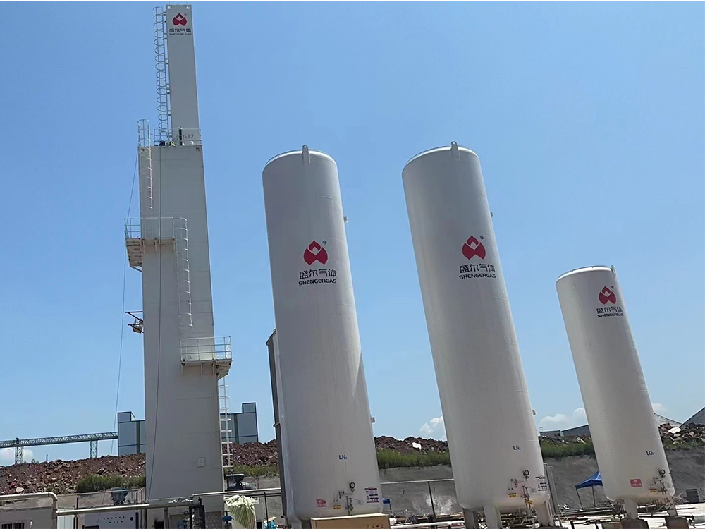
- Recompression and delivery: The gaseous products may be compressed to pipeline pressure. Liquefied products (liquid oxygen, liquid nitrogen, liquid argon) are subcooled if needed and sent to storage tanks.
Throughout this process, tight thermal integration is critical. The multi-stream heat exchanger (MHE) in the cold box typically achieves a cold-end approach of only 2–4 K between incoming cold and outgoing hot fluids. Modern ASUs often incorporate one or more expansion turbines: expanding air through a turbine generates refrigeration and may produce shaft power to assist driving the air compressor (reducing net electrical power).
Different configurations allow Cryogenic Air Separation Units to meet capacity, purity, and energy targets for a wide range of industrial applications.
Typical Plant Design and Operating Parameters
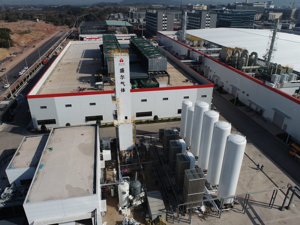
Large-scale cryogenic ASUs (like those supplied by Linde, Air Liquide, Messer, etc.) range from several hundred tons per day (tpd) of oxygen up to several thousand tpd. All such plants share a common engineering “block diagram,” though detailed designs vary by supplier. Key design parameters and operating ranges include:
- Feed air pressure: The compressor elevates air to approximately 5–8 bar gauge before entering the cold box. Higher pressure generally improves separation efficiency but costs more compression energy. (Typical modern ASUs use ~6 bar.)
- Purification: Dual-bed molecular sieves (zeolites) clean the air to dew points of –60 °C or lower, ensuring CO₂ and H₂O are effectively removed. Bed regeneration uses waste gas.
- Heat exchanger approach: Plate-fin exchangers achieve cold-end temperature approaches around 2–4 K. Tight pinch improves efficiency but risks freeze-out if too low.
- High-pressure (HP) column pressure: About 5–6 bar(a). At this pressure, boiling points shift higher (nitrogen might boil around –145 °C and oxygen around –170 °C), but the exact temperatures depend on the operating conditions.
- Low-pressure (LP) column pressure: Roughly 1.1–1.4 bar(a). These near-ambient pressures allow reaching nitrogen’s normal boiling point (~–196 °C) at the top.
- Product purities: Gaseous oxygen is typically delivered at 95–99.5+% purity. For most industrial uses (metallurgy, combustion), 90–98% O₂ is common; many ASUs are configured for ≥99.5% for specialty applications (medical, chemicals). Nitrogen can be produced from about 99.9% up to ultra-high purities (99.9999%) depending on demand. Argon (if recovered) is typically 99%–99.99% pure; ultra-pure argon (for electronics or lighting) may reach 99.999% or higher with additional column steps.
- Recovery rates: Oxygen recovery is the fraction of feed oxygen recovered as product. In a high-purity O₂ plant, recoveries might be on the order of 60–85% (trading off against purity and energy). Nitrogen recovery is usually higher (often 80–95%) because nitrogen is in excess; much of the nitrogen leaves as the top vapor. Argon recovery from an argon column can reach ~80–90% of the argon in the feed air. (If no argon column is used, argon exits with the waste nitrogen stream, and the “recovery” is essentially zero.)
- Specific energy: Cryogenic ASUs are energy-intensive. Modern, well-designed large units typically consume on the order of 200–250 kWh of electrical energy (plus fuel for any power generation) per ton of oxygen produced (at moderate delivery pressure). Smaller or higher-purity units use more energy per ton. Advanced designs with efficient expanders, low-temperature approaches, and heat recovery strive to minimize this consumption.
A sample of typical design and performance values is given in the table below:
| Parameter | Typical Range / Value |
|---|---|
| Feed air pressure (to cold box) | 5.0 – 8.0 bar(g) |
| HP column pressure | ≈ 5.5 – 6.5 bar(g) |
| LP column pressure | ≈ 1.1 – 1.4 bar(g) |
| Cold-end temperature approach (ΔT) | 2 – 4 K |
| Gaseous oxygen purity (O₂) | 95.0 – 99.5% (99.5%+ for high-purity plants) |
| Gaseous nitrogen purity (N₂) | 99.9 – 99.999%+ |
| Argon purity (when recovered) | 96.0 – 99.999% |
| O₂ recovery (high-purity mode) | ~60 – 85% of O₂ in feed |
| N₂ recovery | ~80 – 95% of N₂ in feed |
| Ar recovery (with argon column) | ~80 – 90% of Ar in feed |
<!– skip citation –>
These values depend on design choices. For example, column pressures reflect a trade-off: higher HP column pressure (and corresponding HP reboiler temperature) reduces compressor work but forces a larger temperature lift in the HP-LP column exchanger. The cold-end temperature approach (pinch) is kept above ~2 K to prevent trace impurities from freezing in the heat exchanger. Modern ASUs often use structured packings in columns, which provide efficient mass transfer at lower pressure drops.
Equipment and Flow Sequence
A typical industrial cryogenic ASU comprises the following major equipment:
- Air compressor: Multi-stage integrally geared or turbo compressors bring ambient air to design pressure (often with inter-stage cooling to remove most of the heat of compression).
- Molecular sieve adsorbers: Two (or more) parallel beds alternately remove H₂O, CO₂ and hydrocarbons. The beds are regenerated by waste nitrogen or compressed air.
- Plate-fin heat exchangers (MHE): Large aluminum plate-fin units cool the purified air to cryogenic temperatures and prewarm product streams. They require robust design for high pressure and low temperature service.
- Turboexpanders: High-speed expansion turbines provide the bulk of refrigeration. Some ASUs include a back-compression expander that uses the expander shaft to drive part of the air compressor, recovering shaft power.
- High-pressure distillation column: Typically a tall insulated column (often housed in a cold box) with trays or packing. It separates oxygen-enriched liquid (bottom) from nitrogen-rich vapor (top).
- Low-pressure distillation column: Operates at near-ambient pressure, further purifies the oxygen and concentrates argon. It often works in tandem with the HP column (their condenser/reboiler are thermally connected).
- Argon column (if present): A third column for argon recovery, fed from the LP column’s middle section. Argon distillation requires a high reflux ratio (low product flow) to achieve purity. Modern plants use multiple-column or double-multiple-effect designs to improve argon yield.
- Product compressors and subcoolers: For gaseous delivery, product compressors boost gas to pipeline pressures. For liquid products (LOX, LIN, LAR), cryogenic pumps and subcoolers adjust liquid pressure and temperature for storage.
- Instrumentation and control system: Advanced Distributed Control System (DCS) manages hundreds of control loops (column pressure, flow, temperature, etc.). Modern plants use model-predictive control (MPC) to optimize energy use and maintain product stability during load changes.
Operational Flow (summarized): Atmospheric air is drawn in, filtered, compressed, dried (molecular sieves), then enters the main heat exchanger. There it is cooled to its dew point (~–190 °C). The resulting liquid-vapor mixture enters the HP column: nitrogen-rich vapor exits the top and is vented or sold, while oxygen-rich liquid goes to the LP column. The LP column boils this liquid: gaseous oxygen exits the top, while liquid oxygen (and argon) collects at the bottom. If argon is produced, the LP column side-draw goes to an argon column, which yields purified argon product. Final product gases are warmed back to ambient temperature, and liquids are pumped to storage.All of these tightly integrated processes show how Cryogenic Air Separation Units efficiently convert atmospheric air into essential industrial gases.
Core Air Products: Oxygen, Nitrogen, and Argon
The main products of a cryogenic ASU are oxygen (O₂), nitrogen (N₂), and often argon (Ar). Their specifications depend on end-use:
- Oxygen (O₂): Used in steelmaking, glass, welding, medical, and chemical oxidation. Industrial oxygen is typically ~90–98% pure. Many ASUs operate at ~99.5% purity for broad applications. Ultra-high-purity oxygen (> 99.9%) is possible but requires additional reflux and energy. Gaseous oxygen is often delivered at pressures from near-atmospheric up to 10 bar (on-site compression), or stored as liquid in cryogenic tanks. Typical oxygen production scales are from a few tonnes per day (medical mini-plant) up to several thousand tpd for large industries.
- Nitrogen (N₂): The most abundant product, used for inerting, blanketing, cooling (cryogenics), and as feedstock for ammonia. Bulk nitrogen purity is usually ~99.9–99.99%. For semiconductor or specialty uses, purity may be 99.999% or higher (ultra-high purity nitrogen plants exist, often using additional polishing). Nitrogen is supplied as gas (to pipelines or applications) or as liquid (LIN) in insulated tanks. Large ASUs might produce hundreds to thousands of tonnes per day of N₂ (since ~75% of air is N₂).
- Argon (Ar): A valuable rare gas used in metallurgy (welding), lighting, and electronics. Air contains ~0.93% argon. Typical ASUs recover argon only if there is sufficient demand. When recovered, argon is produced at ~98–99.99% purity. Many ASUs aim for ~99.9% Ar; high-end plants exceed 99.99%. Argon is often delivered as a liquid since gas pipelines for argon are rare. A well-designed ASU with an argon column can recover 80–90% of the feed argon. If argon is not collected, it simply leaves with the nitrogen vent at ~0.5–1% concentration.
In addition to these, very large multi-product ASUs may co-produce trace rare gases (neon, krypton, xenon) at very small rates, but these require extra columns and are specialized facilities. Helium is not obtained from air and is not a cryogenic ASU product.
Design Considerations and Trade-offs
Designing a large ASU involves many trade-offs:
- Purity vs. recovery: Achieving higher product purity usually lowers the recovery and raises energy consumption. For example, boosting O₂ purity above 99% requires extra reflux and more energy, and sacrifices some O₂ yield. Engineers balance purity requirements with operating cost.
- Column pressures: Higher HP column pressure reduces compressor power per unit production but requires more refrigeration (higher reflux ratio) to achieve separation. Lower pressure widens the temperature difference between columns, making the cold-box design more challenging. Typical choices are around 5.5–6.5 bar for HP and 1.2–1.4 bar for LP.
- Equipment design: Plate-fin heat exchangers are favored for compactness and high effectiveness, but require precise manufacture and high-purity brazing. Columns may use structured packing (for low pressure drop) or sieve trays. Materials must be oxygen-service compatible (stainless steel or copper-nickel alloys) to avoid ignition risks.
- Safety: ASUs handle flammable (oxygen) streams at high pressure. All oxygen-containing equipment must be cleaned of hydrocarbons, and valves/instruments must have oxygen-compatible lubricants or be oxygen-cleaned. Relief systems and gas analyzers protect against over-pressurization and trace impurities. CO₂ or H₂O inadvertently frozen in the cold-box can cause blockages or pressure surges, so molecular sieve beds must be well-designed.
- Turn-down and flexibility: Many applications require variable production rates. Modern ASUs incorporate variable inlet guide vanes, load control strategies, and sometimes parallel compression trains to handle partial loads efficiently. Control systems monitor heat-exchanger profiles, column pressure, and product purity to keep balance.
Innovations: Smart Controls, Energy Recovery, and Modular Plants
Recent developments have made ASUs more efficient, safer, and quicker to deploy:
- Smart control systems: Advanced process control (APC) and model predictive control (MPC) algorithms are increasingly used in ASUs to optimize operation. These controls adjust flows, pressures, and temperatures in real time to maximize efficiency or ramp production without operator intervention. Online analyzers and digital twins enable predictive maintenance (anticipating column fouling or compressor issues). Some ASUs feature integrated control dashboards that monitor energy usage (benchmarking kWh/ton) and allow fine-tuning of purge/return flows for minimal wastage.
- Energy recovery: The inherent refrigeration of a cryogenic ASU is mostly provided by turboexpanders, but additional strategies boost efficiency. For example, some plants use the cold produced by the ASU to support LNG regasification or oxygen liquefaction elsewhere. Conversely, waste heat from compressors can be fed into an Organic Rankine Cycle (ORC) to generate electricity. In cogeneration schemes, the ASU’s cold can be used as “thermal storage” for seasonal energy shifting. New architectures even explore reversible processes, where the ASU doubles as a liquid-air energy storage during off-peak electricity times. Overall, best-in-class ASUs now include waste-heat boilers, efficient motors and drives, and finely tuned compressor intercooling to reduce total power consumption.
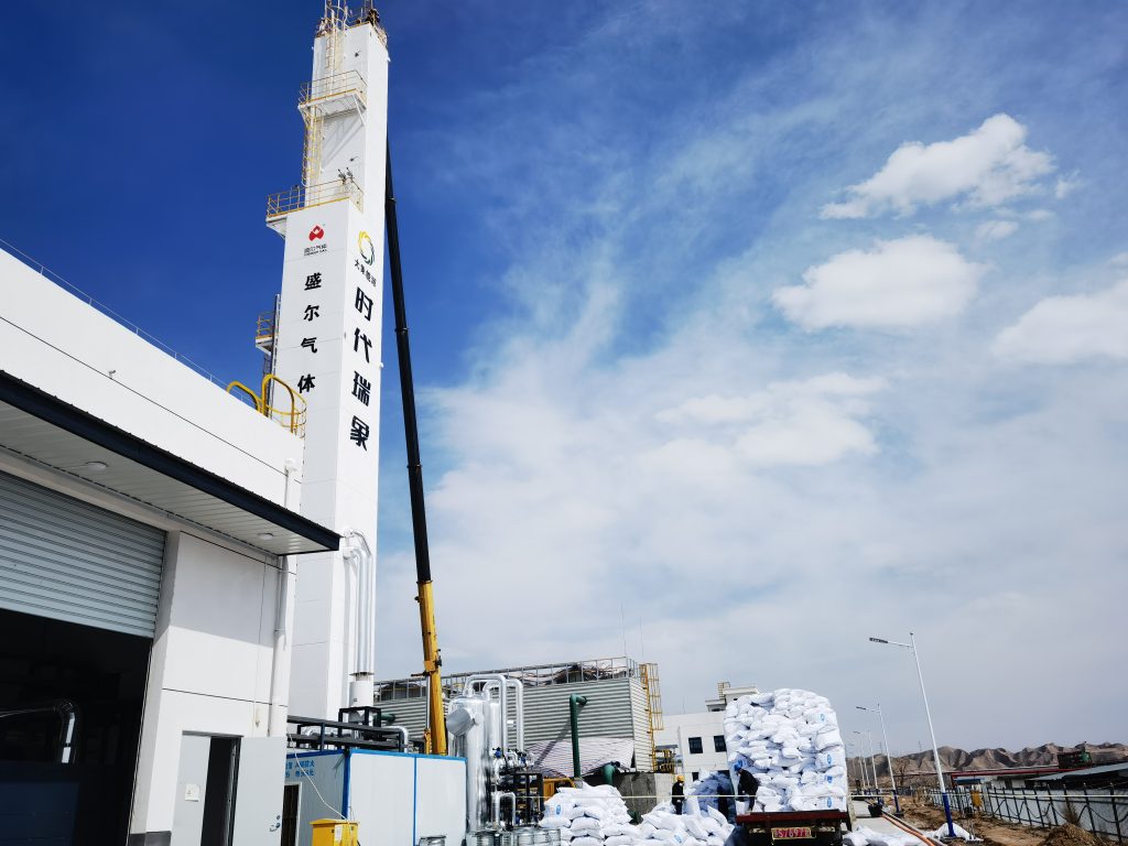
- Modular and compact plants: Suppliers now offer pre-engineered modular ASUs in standardized packages. These cold-boxes, columns, compressors, and control skids are assembled and tested off-site, then shipped for rapid on-site connection. Modular ASUs drastically cut construction time and cost. For example, Linde’s NOVON™ and SPECTRA™ product lines are factory-built modules for oxygen and high-purity nitrogen, respectively. Capacities range from a few thousand Nm³/hr up to tens of thousands. Containerized or skidded plants can provide small-to-medium flow rates with minimal field work. Similarly, advances in plate-fin exchanger design and column erection allow ultra-compact footprints. These modular ASUs are especially popular for remote projects or as “plug-and-play” enhancements to existing facilities.
Additional technological innovations include improved heat exchanger materials (allowing colder approaches), smart safety devices (e.g. fiber-optic leak sensors), and process integration (such as using waste CO₂ from other operations as refrigeration).
Industrial Applications
Cryogenic Air Separation Units are widely deployed wherever large and continuous gas consumption is required.Cryogenic ASUs serve a vast array of industries:
- Metallurgy: One of the largest uses of ASU oxygen is in steel and ferroalloy plants. Basic oxygen steelmaking requires huge flows of ~99% O₂ to support high-intensity oxygen blast. Non-ferrous metal refining also uses O₂ and N₂ (for inerting). Tailored low-purity oxygen ASUs (around 90–97%) are deployed directly at blast furnaces to boost efficiency.
- Oil & Gas and Petrochemicals: Air separation provides oxygen for partial oxidation reactions (ethylene oxide, syngas, hydrogenation), and nitrogen for inert blanketing or purging reactors and pipelines. For example, ethylene oxide plants often have on-site ASUs producing 98–99.5% O₂. Large gas processing complexes install ASUs to supply high-purity oxygen to reformers and nitrogen for enhanced oil recovery (EOR) or pipeline inerting.
- Electronics and Semiconductors: These industries need ultra-high-purity gases. ASUs configured with extra distillation stages supply 99.999%+ N₂ and O₂ (and sometimes Ar) for semiconductor wafer fabrication. Zero ppm hydrocarbon and moisture are maintained through stringent upstream purification.
- Medical and Laboratory: Medical oxygen plants (often in hospital complexes or regional distribution centers) use cryogenic ASUs at moderate scale (hundreds of tons/day O₂) to supply bottled or piped oxygen. Because medical oxygen must meet pharmacopeia standards (often 93–95% for medical, though cryogenic units can easily exceed that), ASUs ensure continuous supply with high purity.
- Food & Beverage: Liquid nitrogen from ASUs is widely used for food freezing and packaging (modified atmosphere). Nitrogen blanketing in fermentation and storage tanks is common. Small modular nitrogen ASUs are now standard on-site for large breweries or food plants.
- Chemical Manufacture: Many chemicals (nitric acid, fertilizers) rely on nitrogen or oxygen. ASUs supply the massive N₂ volumes needed for ammonia synthesis (though these often come from air via partial oxidation, some processes use air separation directly). Specialty chemicals use high-purity O₂/Ar for processes like solvent stripping or blanketing.
- Energy and Environment: ASUs play a role in emerging energy systems. Oxygen from ASUs is key to oxy-fuel combustion and carbon capture schemes. Nitrogen is used for gas turbines as diluent or to enable gasification. Argon is even used in solar photovoltaic manufacturing and lighting. In waste-to-energy plants, ASU oxygen can improve combustion; in biogas upgrading, nitrogen is used for pipeline boosting. Moreover, integration of ASUs with LNG terminals (using cold LNG for refrigeration) is an active area of development, improving overall plant efficiency.
Across these sectors, ASUs may be owned by industrial gas companies (Linde, Air Liquide, Air Products, Praxair, Messer, etc.) or built as captive plants by large consumers. Modern ASUs are often part of broader industrial complexes (steel mills, refineries, chemical parks), supplying multiple units via piping networks.
Conclusion
Cryogenic Air Separation Units are the backbone of industrial gas supply for large oxygen, nitrogen, and argon demands. By leveraging cryogenic refrigeration and distillation, they produce high-purity gases at scales unmatched by other technologies. The principles date back over a century to Linde’s and Air Liquide’s early work, but today’s plants are far more efficient and controlled. Key design choices – column configuration, operating pressures, heat exchanger effectiveness – define performance and cost. In recent years, innovations in automation (smart controls), energy integration (expanders, waste heat recovery), and modular construction have improved ASU flexibility and economics. Whether supporting steel furnaces, chemical reactors, or semiconductor fabs, modern cryogenic ASUs continue to evolve, delivering cleaner production, higher efficiency, and faster project timelines.
Continued research focuses on further energy reduction (through new refrigeration cycles or hybrid systems), digital optimization of operations, and integration with renewable energy and storage systems. For engineers and researchers, understanding ASU fundamentals and keeping abreast of these advances is crucial as demand for industrial gases grows and as the push for lower-carbon processes intensifies.Therefore, Cryogenic Air Separation Units will continue to play a key role in global industrial transformation.
Overall, Cryogenic Air Separation Units remain a mature yet vibrant technology at the intersection of process engineering, thermodynamics, and controls – an essential enabling technology for the world’s industrial infrastructure.


