Introduction
Cryogenic air separation is an essential industrial process for producing high-purity oxygen, nitrogen, and argon by liquefying and distilling air. This process is highly energy-intensive, making energy consumption a critical concern for both economic and environmental reasons. In large cryogenic air separation facilities (also known as air separation units, or ASUs), electricity usage can constitute the majority of operating costs. Optimizing energy use is therefore a top priority for plant operators and researchers. In this article, we present a detailed analysis of energy consumption in cryogenic air separation, focusing on where energy is expended, how much is typically used, and ways to improve efficiency. We will examine the process stages that demand the most power, compare energy usage by component in a technical table, and discuss factors and strategies influencing energy efficiency. The goal is to provide a comprehensive, technically sound overview of energy use in cryogenic air separation for researchers and engineers interested in improving ASU performance.

Cryogenic Air Separation Process Overview
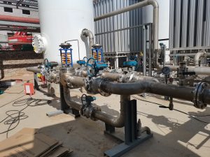
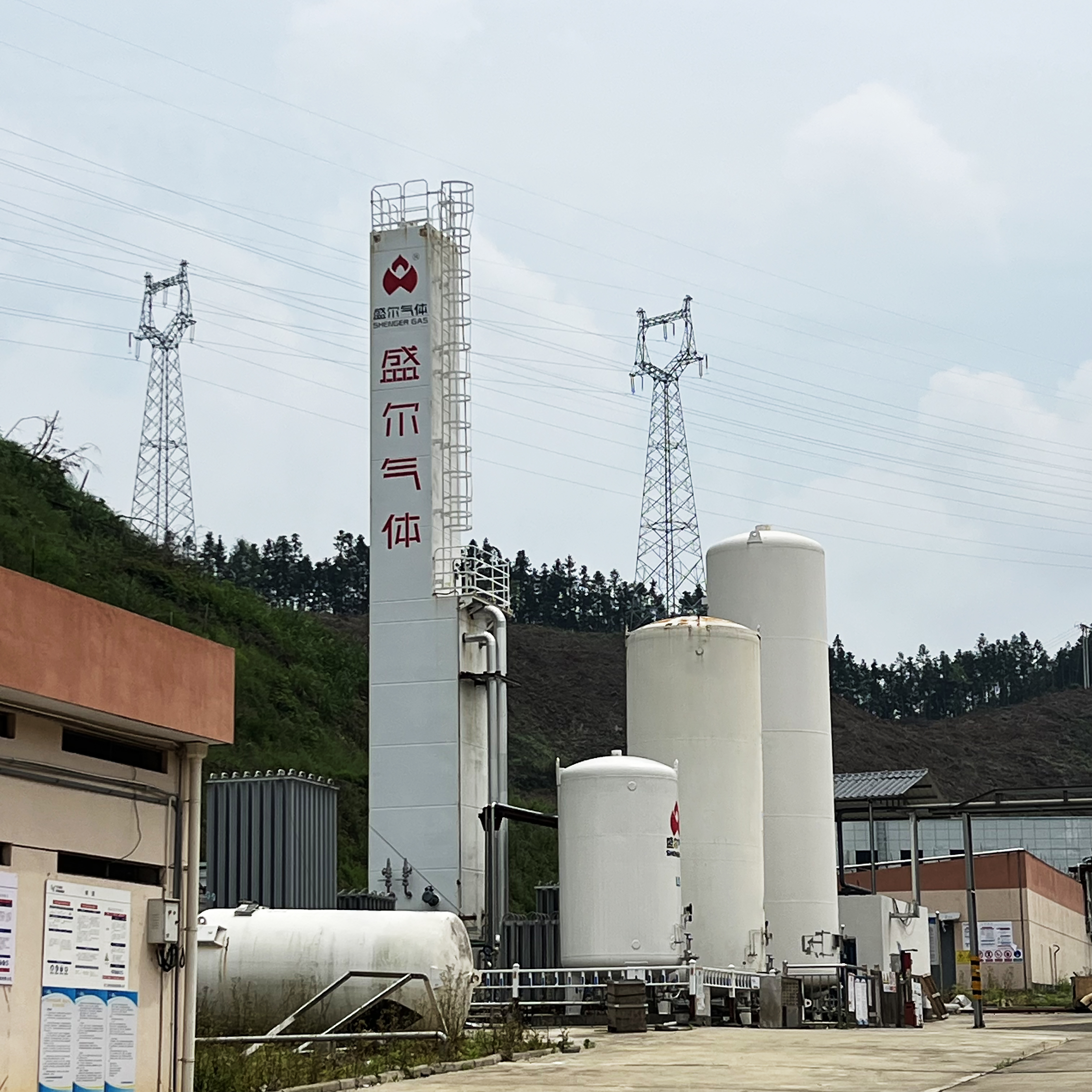
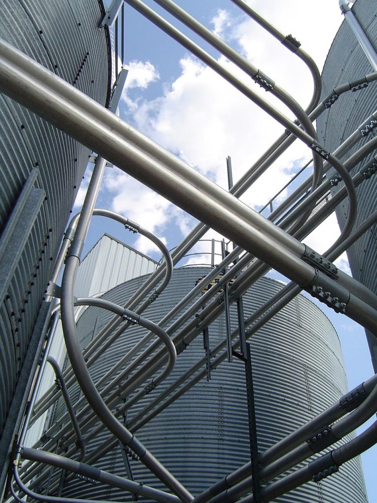
Cryogenic air separation works by cooling air to extremely low temperatures until it liquefies, then separating the liquid air into its components via distillation. The process begins with air compression: ambient air is drawn in and compressed to elevated pressure (often on the order of 5–8 bar) by a multi-stage main air compressor with intercoolers. This compression step is necessary to enable effective heat exchange and to drive the distillation process, but it requires a substantial energy input. After compression, the air passes through a purification system (typically molecular sieve adsorbers) to remove water, carbon dioxide, and hydrocarbons that would otherwise freeze at cryogenic temperatures. The purified, pressurized air is then cooled to cryogenic temperatures (around –180 °C) in the main heat exchanger. This heat exchanger uses returning cold product streams (and in some designs external refrigerants or cooling loops) to precool the high-pressure air to near its dew point.
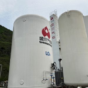
Once sufficiently cooled, the high-pressure air feed is partially liquefied and fed into the distillation system. Modern ASUs use a double-column distillation arrangement: a high-pressure column and a low-pressure column operating in tandem. In the high-pressure (HP) column, the compressed air separates into a nitrogen-rich vapor at the top and oxygen-enriched liquid at the bottom. The nitrogen vapor is then condensed by heat exchange against boiling oxygen-rich liquid from the low-pressure column in a common condenser/reboiler. This condensed nitrogen provides reflux for the low-pressure (LP) column, where it helps strip remaining oxygen out of the nitrogen. In the LP column (operating near 1 atm), high-purity oxygen (~99% O₂) is obtained as liquid at the bottom, and high-purity nitrogen (~99.9% N₂) comes off as gas at the top. Many large ASUs also incorporate an argon side column to extract argon (which accumulates between the nitrogen and oxygen boiling points) without sacrificing oxygen purity. Throughout this cryogenic distillation process, refrigeration must be continuously provided to balance heat leaks and the cooling needs of boiling and condensing fluids. Refrigeration is typically generated by expanding a portion of the compressed air through a turbo-expander (also called an expansion turbine). The expansion cools the gas (the Joule–Thomson effect enhanced by doing external work), producing the low temperatures required for liquefaction. The expander may drive a generator or booster compressor, recovering some work, but a significant net energy input is still needed to maintain the cryogenic conditions.
In summary, the key operations of a cryogenic air separation plant are air compression, purification, cryogenic cooling, distillation (in multiple columns), and product extraction. The energy use is dominated by mechanical work inputs: running large compressors, turbo-expanders, pumps, and associated systems. Virtually all of this energy ultimately appears as heat that must be removed (for example, intercoolers removing compressor heat and cold boxes absorbing the refrigeration load). Understanding how this energy is distributed across the process stages is crucial for analyzing efficiency and identifying improvements.
Energy Consumption in Cryogenic Air Separation
Energy consumption in cryogenic air separation is usually measured in terms of specific power: the kilowatt-hours of electricity required to produce a unit quantity of product (often expressed per ton of oxygen produced, since oxygen is a primary product). Thermodynamically, separating air into pure components has a significant minimum energy requirement. For example, the theoretical minimum work to isolate 1 metric ton of oxygen from air (starting at ambient conditions) is on the order of 50–60 kWh. This represents an ideal reversible process with no losses. In reality, actual cryogenic ASUs consume several times this theoretical minimum due to irreversibilities in compression, heat exchange, and expansion. Modern large-scale plants typically require roughly 4 times the thermodynamic minimum. In practical terms, a state-of-the-art cryogenic air separation unit might use around 200 kWh of electricity per ton of O₂ produced (exact values vary with plant design and conditions). Some highly optimized mega-scale facilities have achieved specific power as low as ~170–180 kWh/ton O₂, whereas older or smaller ASUs may be in the 250–300+ kWh/ton range. These figures include the energy for producing not just oxygen but also co-products (nitrogen and argon) in the desired purities and delivery pressures.
Several factors explain why actual energy use is much higher than the ideal minimum. Compressor inefficiency and heat losses: Multi-stage compressors approach, but never reach, ideal isothermal compression; energy is lost as heat that must be removed by intercooling. Pressure drop and heat exchanger temperature differences: In the real plant, fluids flow through pipes, valves, and exchangers with finite pressure drops, and heat exchangers require temperature gradients to drive heat transfer. These effects increase entropy and therefore require extra work input compared to an ideal process. Finite refrigeration cycles: The production of refrigeration via expansion cannot recapture all the work input (turbo-expanders have limited efficiency and some cooling is achieved by throttling Joule–Thomson valves which dissipate work entirely). Additionally, auxiliary equipment like pumps, fans, and control systems consume power. All these inefficiencies add up across the process.
It’s also important to note how operating conditions and product requirements influence energy consumption. Higher product purity demands more reflux and often more stages of distillation, which can increase energy use per unit of product. For instance, producing oxygen at 99.9% purity will consume more energy than producing 95% purity oxygen, because additional refrigeration and reflux are needed to squeeze out the last impurities. Product delivery pressure is another factor: if oxygen or nitrogen must be delivered at high pressure, either the entire ASU operates at higher pressure or additional compressors/pumps are used on the product streams, both of which raise energy requirements. Despite these challenges, the efficiency of cryogenic air separation has improved steadily over the decades through better components and smarter cycle designs. Larger plants tend to be more energy-efficient (per unit output) than smaller ones, because scale allows for more effective heat integration and lower relative heat losses. Today’s best industrial ASUs have brought the specific energy consumption closer to the fundamental limits than ever before. The following section breaks down the energy usage by major process components to highlight where the power goes within a cryogenic ASU.
Energy Use by Process Stage and Component
Not all parts of the cryogenic air separation process consume equal amounts of energy. In fact, the majority of the power input is concentrated in a few key areas. Table 1 below summarizes a typical distribution of energy use by major process stage/component in a modern cryogenic air separation plant:
| Process Stage / Component | Approx. Share of Total Energy Consumption |
|---|---|
| Air compression (main air compressor) | ~50–60% (dominant portion) |
| Cryogenic refrigeration (expanders, JT valves) | ~20–30% |
| Product gas compression or liquid pumping | ~10–20% (depends on required delivery pressure) |
| Other auxiliaries (cooling fans, pumps, controls) | ~5–10% |
Table 1: Typical energy consumption breakdown by process stage in a cryogenic air separation unit.
In most ASUs, the main air compressor is by far the single largest consumer of electricity. Compressing the enormous volume of air required for the distillation columns (often thousands of cubic meters of air per hour in large plants) accounts for roughly half or more of the total power draw. This includes any booster compressors for feeding turbo-expanders or maintaining column pressure. The compressed air must later be cooled to cryogenic temperatures, but the initial compression work represents a high-grade energy input that largely ends up as waste heat removed by intercoolers. The next significant chunk of energy goes into the refrigeration system. The refrigeration duty in an ASU is met by one or more turbo-expanders (and in some cases supplemental Joule–Thomson expansion valves). These devices provide the cold temperatures necessary for liquefying air and sustaining the distillation. The turbo-expander essentially converts some of the air’s pressure energy into refrigeration by doing work (often recovering a small fraction of that work as usable energy to drive a generator or an auxiliary compressor). Nevertheless, providing adequate refrigeration might consume roughly a quarter of the plant’s total power. The share can vary depending on how much heat integration is implemented and the ambient conditions – for example, a plant in a hot climate or one producing very low temperature liquid products might need a higher refrigeration load.
Product compression and pumping constitute the next portion of energy use. If the ASU outputs gaseous products at pressure (for instance, oxygen delivered to a pipeline at several bars, or nitrogen compressed for storage or use), additional compressors are used to pressurize these product gases. In some modern designs, liquid pumping is employed instead of gas compression (for example, pumping liquid oxygen to high pressure and then vaporizing it, which is more energy-efficient and avoids handling high-pressure O₂ gas). In either case, providing product pressure or moving liquid product through the system will consume roughly 10–20% of the total energy, depending on the required pressures and flow rates. In plants where only low-pressure products are needed (e.g. supplying oxygen at near-atmospheric pressure to a combustion process on-site), the product compression load might be negligible, whereas in an application like an oxy-fuel combustion power cycle that needs very high-pressure O₂, the product compression/pumping can be a substantial part of the energy budget.
Finally, the auxiliary systems make up the remainder of the energy consumption (typically under 10%). These include various pumps (for circulating cooling water, pumping liquid nitrogen or argon, etc.), fans (for cooling towers or air coolers), as well as instrumentation, control systems, and losses in electrical equipment. While each of these is comparatively small, together they are non-trivial and efficient design should not ignore them. For instance, pumping cryogenic liquids through the cold box with minimal pressure drop and using efficient motors can slightly reduce the overall power requirement.
This breakdown makes clear that improvements in the air compression and refrigeration stages will yield the largest gains in reducing energy use, since they dominate the consumption. It also highlights that the distillation itself (the separation inside the columns) does not directly consume electrical energy – rather, its impact on energy use is indirect, by influencing how much compression and refrigeration are needed. With an understanding of where the energy is going, we can examine what factors affect the efficiency of these stages and what strategies can reduce the overall power consumption.
Factors Influencing Energy Efficiency
Several key factors determine the energy efficiency of a cryogenic air separation process. Understanding these factors is important when analyzing or comparing ASU performance:
- Scale of Plant: Larger ASUs tend to achieve lower specific energy consumption (kWh per unit of product) than smaller plants. Economies of scale allow for more effective heat integration and relatively lower heat losses. For example, doubling production capacity does not double the heat leak or inefficiencies, so bigger plants can produce oxygen and nitrogen more efficiently. Over the past few decades, the trend of building larger single-train ASUs (several thousand tons per day of oxygen) has contributed to improved energy efficiency.
- Operating Pressure: The pressures at which the air is compressed and the distillation columns operate have a direct impact on energy use. Higher air inlet pressure can reduce the size of equipment and improve refrigeration capacity, but it also means more work is spent in compression. Optimizing the high-pressure column pressure is a balancing act: too high and you waste compression energy; too low and you may not have enough driving force for heat exchange between columns. Many modern designs use the lowest feasible air pressure (~4–6 bar range) that still allows sufficient refrigeration and reasonable column sizes, thereby saving energy in compression.
- Product Purity and Recovery: The required purity of oxygen, nitrogen, and argon influences how the plant is configured and how much energy it uses. Achieving ultra-high purities (99.9%+ O₂ or N₂) demands more reflux and often additional distillation steps or columns (like an argon column for oxygen purity). Each extra step or higher reflux ratio means more cooling duty and sometimes more compression. If the end-use allows a slightly lower purity (say 95% O₂ for certain combustion processes), the ASU can be run more efficiently, shaving off a portion of the energy use. There is typically a trade-off between purity and power consumption: beyond a certain point, every incremental gain in purity comes with a disproportionately large increase in energy input.
- Product Delivery Pressure: As mentioned, if the gaseous products must be delivered at high pressure, significant energy is spent either in boosting the whole cycle pressure or in compressing the products after production. For instance, supplying oxygen at 30 bar for gasification will consume much more energy than supplying oxygen at 1 bar for a metallurgical furnace. Design choices like internal compression (pumping liquid oxygen to high pressure then vaporizing it) can mitigate some of this energy cost compared to compressing gaseous oxygen, but at the expense of more refrigeration duty to produce that liquid. Ultimately, the required output pressure of products is a major factor in the ASU’s overall energy requirement.
- Ambient Conditions and Heat Integration: The environment in which the ASU operates affects its efficiency. Higher ambient temperatures make intercooling and heat rejection less effective, potentially requiring more work from refrigeration systems. Humid or dirty air can increase purification burdens or pressure drops. On the other hand, an ASU can sometimes benefit from integration with other processes – for example, using waste heat from compressors in other parts of a plant, or employing external cold sources (like LNG regasification cold energy) to assist in refrigeration. Good heat integration within the ASU (such as recovering and reusing as much cold energy as possible between streams in the heat exchanger) is also critical to minimize wasted energy. Designs that minimize temperature differences in the heat exchangers and efficiently capture the cold from expanded streams will perform closer to the thermodynamic ideal.
By carefully considering these factors during design and operation, engineers can identify where inefficiencies arise and target those areas for improvement. For instance, if analysis shows that the main compressor is expending excess energy due to higher-than-needed discharge pressure, the operating strategy can be adjusted. Or if a plant is operating in a warm climate, additional intercooling or an enhanced cooling system might be justified to keep compression power in check. Ultimately, the energy efficiency of cryogenic air separation is a result of both engineering design decisions and operational choices in response to these influencing factors.
Strategies to Reduce Energy Consumption
Driven by the high cost of energy, many strategies have been developed to reduce power requirements in cryogenic air separation without sacrificing output or safety. Below are several proven or emerging approaches for optimizing ASU energy use:
- High-Efficiency Compression: Because air compression is the largest energy sink, improvements here yield big returns. This includes using modern centrifugal or axial compressors with high isentropic efficiency, employing multiple stages with inter-stage cooling to approach isothermal compression, and using variable speed drives (VSDs) to adjust compressor speed to match demand (avoiding energy waste during partial load operation). Keeping the compressor inlet air as cool and clean as possible (for example, using intake chillers or good filtration) also helps, since cooler air is denser and requires less work to compress a given mass. Some advanced ASUs use “ultra-low” feed pressure designs, where the main air compressor discharge pressure is minimized (e.g. ~0.4 MPa instead of 0.6 MPa) – this must be matched with very efficient cold recovery in the distillation columns, but it dramatically cuts compressor power needs.
- Enhanced Refrigeration Cycles: Improving the refrigeration generation can reduce the energy needed for cooling. One strategy is to maximize turbo-expander energy recovery – using expansion turbines to not only produce cold, but also to do useful work (like driving a helper compressor or generator). This effectively recycles some energy back into the system. Utilizing multiple expansion stages (high-level and low-level expanders) can also yield colder temperatures more efficiently than a single stage. Optimizing the Joule–Thomson (JT) valves and expanders in the cold box can ensure the right balance between turbine expansion and simple throttling, so that exergy losses are minimized. In some designs, external refrigeration loops (e.g. a nitrogen recycle refrigerator or even mechanical chillers for pre-cooling) are used to offload some of the work from the main ASU process if that proves more efficient under certain conditions.
- Process Integration and Heat Exchanger Optimization: A well-integrated heat exchanger network in the cold box is vital for energy efficiency. Plate-fin heat exchangers with very small temperature approach differences (on the order of 1–2°C at the cold end) help recover as much cold energy as possible between streams. Reducing the temperature difference means less entropy generation and closer-to-ideal performance. Additionally, minimizing pressure drop in these exchangers and throughout the cold box ensures that the compressor isn’t doing extra work just to overcome frictional losses. Some new ASU designs feature improved core-in-shell or brazed aluminum exchangers and streamlined piping to cut down pressure losses. Effective heat integration also extends to the rest of the plant: for example, using the waste heat from compressor inter-coolers to regenerate the molecular sieve beds (used for air purification) – this way, heat that would otherwise be discarded is put to use, reducing the need for electric heaters during sieve regeneration.
- Advanced Control and Load Management: Smart control systems can save energy by keeping the ASU operating at optimal setpoints and efficiently handling load changes. Model predictive control (MPC) and real-time optimization software can adjust variables like column pressures, reflux rates, and expander flows to minimize power use for the required production rate. During periods of lower demand, controls can safely turndown the plant and perhaps idle certain equipment, preventing unnecessary power draw. Conversely, during peak demand, an optimized control strategy will ensure no energy is wasted in over-purifying or over-compressing beyond what’s needed. Some plants also take advantage of variable electricity pricing by ramping up production (and power consumption) when electricity is cheaper (off-peak hours) and slowing down when prices are high, effectively “shifting” energy use to reduce cost without changing total production. This operational strategy doesn’t reduce kWh per ton, but it lowers energy cost per ton, which is often just as critical in practice.
- Internal Compression and Improved Equipment: In scenarios where very high-pressure oxygen is needed (for example, oxy-combustion power cycles or gasifiers), internal compression methods can reduce energy use. Pumping liquid oxygen or nitrogen to high pressure requires far less energy than compressing the equivalent gas, due to the much higher density of the liquid phase. Modern ASUs designed for such duties may include cryogenic liquid pumps that boost product pressure to dozens of atmospheres, eliminating the need for massive gas compressors on the product. This strategy must be accompanied by robust safety measures (handling pressurized cryogenic fluids) and sufficient refrigeration capacity to produce the liquid in the first place, but it can cut specific energy consumption significantly for high-pressure outputs. Additionally, ongoing improvements in machinery (from more efficient expanders and compressors to low-loss molecular sieve valves) and in insulation (reducing heat leak into the cold box) all contribute to incremental energy savings over time.
By combining these strategies, new cryogenic air separation plants are far more energy-efficient than earlier generations. Even existing plants can often be retrofitted or re-optimized: for example, adding a variable speed drive to an older compressor, or revamping the cold box internals to reduce bottlenecks, can yield measurable reductions in power consumption. Given that energy costs typically dominate ASU operating expenses, the payback period for such optimizations is usually favorable. Moreover, reducing energy use in cryogenic air separation not only cuts costs but also lowers the environmental footprint (since it often correlates with lower CO₂ emissions for a given amount of product when the power grid has fossil-fuel generation).
Conclusion
Energy use in cryogenic air separation is a central factor in the design and operation of air separation units. Through a detailed review, we have seen that the cryogenic air separation process, while highly effective at producing ultra-pure industrial gases, requires substantial energy input primarily for compressing air and providing refrigeration. The analysis shows that the main air compressor and refrigeration stages typically consume the bulk of the power, with smaller contributions from product compression and auxiliary systems. We discussed how the overall specific energy consumption for cryogenic air separation has been driven down closer to the theoretical limits over the years – modern large ASUs might use roughly 200 kWh per ton of oxygen, compared to the ~50 kWh per ton thermodynamic minimum, indicating the progress made through better engineering. We also explored various factors that affect energy efficiency (such as plant scale, operating pressures, product specifications, and ambient conditions) and outlined strategies to further reduce energy usage, ranging from advanced compression techniques and heat integration to smart controls and novel process tweaks.
In summary, a cryogenic air separation plant’s performance and viability are tightly linked to its energy consumption profile. For researchers and technical personnel working with ASUs, focusing on energy consumption analysis is crucial. By carefully monitoring where energy is spent and employing optimization strategies, significant improvements can be achieved – lowering operating costs, enhancing sustainability, and increasing the competitiveness of this mature but continually evolving technology. As energy prices and environmental pressures rise, the drive to make cryogenic air separation more efficient will remain a key priority, spurring ongoing innovations in process design and equipment efficiency. Each incremental gain in reducing energy use brings the process closer to its theoretical ideal and delivers substantial economic and environmental benefits to industries that rely on cryogenic air separation.