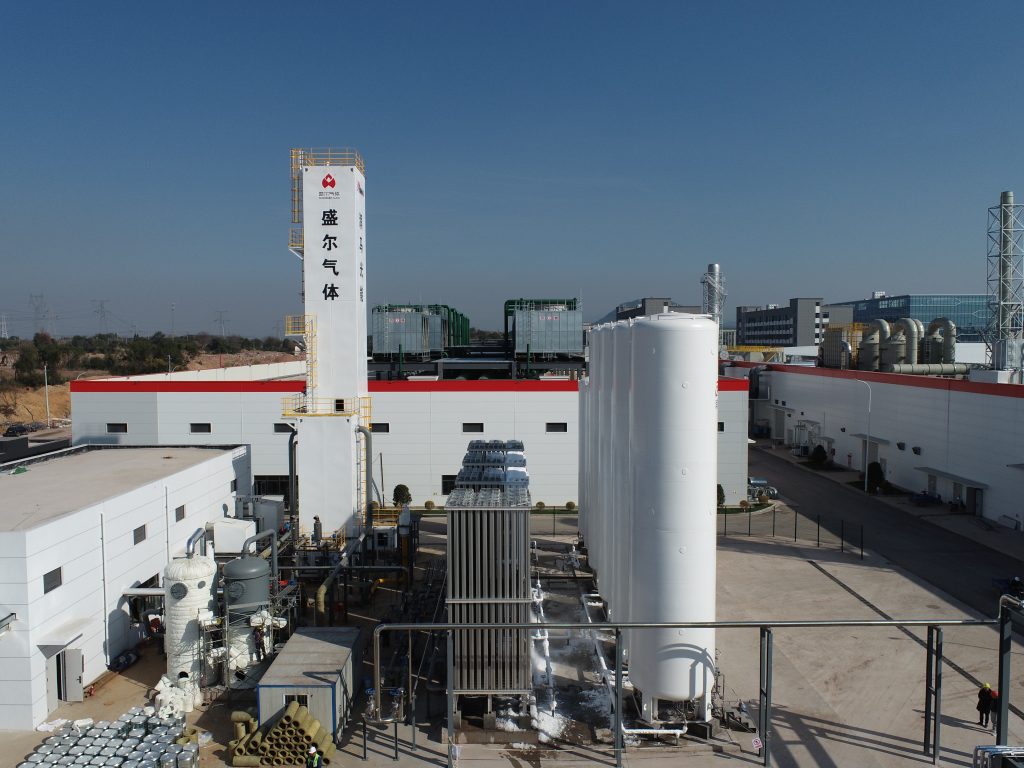
工业氧气和氮气的大量、连续供应通常采用低温空气分离技术生产。其原理步骤很简单:净化空气,将其冷却至一部分液化,然后通过蒸馏分离氮气和氧气。实际上,该装置是一个紧密耦合的制冷和分离系统——这意味着热端的微小压降、微量污染或控制选择都会影响冷端的纯度、回收率和能耗。因此,提高低温空气分离效率的关键在于控制整个冷箱的压降、夹点温度以及可避免的节流损失。
本文概述了从压缩到双塔精馏的整个过程,并从工程角度进行了阐述。其目标是将热力学和传质原理与研究人员和工厂工程师真正关心的实际约束条件联系起来:干燥度和洁净度、主换热器夹点、膨胀机功回收、塔耦合以及确保空分装置在环境波动和负荷降低情况下保持稳定的运行裕度。
1)空气压缩:定义压力架构
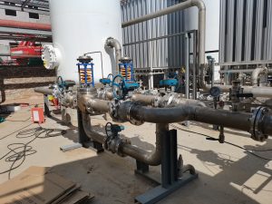
热端流程始于过滤,对于大型工厂,则采用带中间冷却的多级离心式主空气压缩机。压缩不仅仅是为了输送气流;它决定了整个流程的压力“架构”。更高的压力可以简化一些制冷和液化步骤,但会增加压缩机的做功,并放大下游压降带来的能量损失。
后冷却器带走压缩产生的热量,并冷凝大部分进气水分。有效的除湿和排水可以降低吸附床的负荷,并减少后续结冰的风险。对于变负荷运行,喘振控制、进气导叶设计以及压缩机特性曲线的选择与多变效率同样重要。
2)预纯化:防止冻裂和结垢
在深度冷却之前,必须去除空气中在低温下会凝固的物质。水和二氧化碳是主要目标;根据现场空气质量和碳氢化合物风险管理情况,可能还会监测痕量有机物和一氧化二氮。现代工厂通常使用变温吸附(TSA)预净化装置(PPU),该装置采用分子筛,分子筛以两层(或更多层)床层的形式排列,在吸附和再生之间循环。
在吸附过程中,冷却的压缩空气依次通过保护层(通常为活性氧化铝)和沸石层,沸石层能将H₂O和CO₂吸附至极低的残留水平。在再生过程中,高温干燥气体(通常为废氮气)会解吸杂质并恢复吸附能力。在低温空气分离中,尤其对于全年运行的装置而言,压力处理单元(PPU)是可靠性的关键:穿透会导致狭窄通道结冰、压降升高、传热性能下降,最终需要强制升温。
3)主换热器:低温空气分离过程中“冷量”在此处得以保存或损失。
主换热器 (MHE) 是低温空气分离 (ASU) 的热力核心。大型 ASU 通常采用多通道铝板翅式换热器,冷却进入的空气,同时加热排出的产品和废液。一个设计良好的 MHE 可以回收大部分排出氮气和氧气中的冷量,因此净制冷主要用于液化过程和不可逆过程(压降、热泄漏、有限的温差)。
在实际应用中,主要有两个设计约束。首先是最小温差(夹点):降低夹点可以降低功率,但会增加换热器尺寸,并提高其对分配不均的敏感性。其次是压降:冷箱的额外压降并非局部性的——它会反过来影响所需的压缩机压头,并改变有效塔压。因此,详细的通道布局、翅片选择和分配质量被视为首要设计决策,而非封装细节。
4)制冷产生:涡轮膨胀加节流
为了达到冷端,装置必须产生制冷。涡轮膨胀机通常是主要设备,因为它在产生冷量的同时还能从气体中提取能量。这些能量可以在制动压缩机或发电机中回收,从而提高整体效率。膨胀机的入口温度、压力比和等熵效率在很大程度上决定了有多少原料可以被液化,以及在负荷变化期间冷平衡的稳定性。
焦耳-汤姆逊节流(JT)也常用于冷平衡调节以及在有利条件下产生额外的液体。与膨胀机不同,JT阀不产生轴功,因此作为制冷源的效率通常较低;其优点是结构简单且易于控制。
大型工厂常用的策略是将净化后的空气分成两部分。一部分经过增压/冷却以支持高压塔,另一部分则膨胀至低压状态以产生制冷和部分液化。这种分成是低温空气分离中效率与可操作性之间联系的核心自由度。
5)蒸馏:高压和低压耦合塔
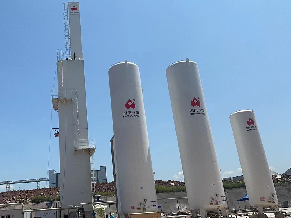
空气部分液化后,通过精馏实现分离。低温空气分离利用氮气和氧气(如果回收,还包括氩气)的挥发性差异。由于相对挥发性不高,工业装置通常采用双塔系统:高压塔通过冷凝器-再沸器与低压塔相连。
在高压侧,冷却空气以接近露点的温度进入。富氮蒸汽上升,而富氧液体则向下流过塔板或规整填料,形成内部回流并改善组分分布。来自高压侧塔顶的氮气在冷凝器-再沸器中冷凝。冷凝器-再沸器释放的潜热使低压侧的富氧液体沸腾,从而产生蒸汽流量,无需外部再沸器即可实现高纯度分离。
低压塔的工作压力接近大气压。氮气通常以气态(和/或液态)的形式从塔顶附近抽出,而氧气则以液态的形式从塔底抽出。如果需要加压的氧气,与将氧气压缩到相同的输送压力相比,泵送液氧并在物料交换器 (MHE) 中将其汽化通常在能量上更有利。
如果采用氩气回收,则会增加分离级数,提高对塔内水力学和回流稳定性的敏感性,从而进一步收窄操作窗口。在这些设计中,密封性和稳定的冷平衡与平衡级数同等重要。
6)产品升温、回收以及废物流的作用
产品离开冷端后,在物料交换器 (MHE) 中被加热,并将冷气返回到进入的空气中。目标是在满足输送条件(温度、压力、纯度)的同时,最大限度地减少净冷量损失。氮气可以以气态、液态或两者结合的形式输送。氧气可以以气态、液态或泵送至高压后汽化的液态形式输送。
废氮气并非仅仅是排放物。它通常用于PPU再生、仪器吹扫和密封,并且是稳定塔压和冷凝器负荷(在环境温度波动和调节范围减小的情况下)的实用可控变量。在实验和实际运行中,许多“微小”损失(热泄漏、阀门泄漏、分析仪漂移)都会表现为废液流量的变化以及低温空气分离表观效率的显著改变。
7) 典型操作窗口(双列 ASU)
以下范围代表大型现代化双塔装置的典型值。实际值取决于产品类型(气态产品或液态产品)、集成方式(增压器、膨胀机、液体备用装置)以及现场条件。
| 部分/参数 | 典型范围 | 工程意义 |
|---|---|---|
| 主空气压缩机排气口 | 5–7 bar(a) | 设置高压柱液位;压力越高,压缩机工作量越大。 |
| 高压柱顶压力 | 4.5–6.5 bar(a) | 决定冷凝器-再沸器温度驱动力 |
| 低压塔顶压力 | 1.1–1.4 bar(a) | 影响分离锐度和氧气沸点 |
| 冷端温度,富氮 | ~77–82 K | 随压力和氮气纯度目标而变化 |
| 冷端温度,富氧 | ~88–92 K | 在工作压力下接近氧气沸腾区域 |
| 典型氧气纯度(气体) | 95–99.5 mol% | 纯度越高,通常回流和功率也会增加。 |
| 典型氮气纯度(气体) | 99.9–99.999 mol% | 超高纯度提高了密封性和控制要求。 |
| 指示性比功率 | 0.35–0.65 kWh/Nm³ GOX | 很大程度上取决于规模、副产品和交付压力 |
| PPU出口干燥目标 | ≤ -70 °C dew point | 物料交换器中防止结冰和二氧化碳冻结的裕量 |
8) 提高效率的关键在于:压降、夹点和集成
如果按照热力学第二定律追踪损失,低温空气分离中可避免的不可逆损失主要由压降和有限温度下的热传递造成。物料交换器或塔器中几毫巴的额外压降会导致压缩机排气压力升高,而工厂需要持续为此付出成本。因此,冷箱压降预算通常被视为合同项目,而非“锦上添花”的规格。
物料搬运设备 (MHE) 的夹点策略是另一个关键控制因素。较低的进料温度可以降低功率,但会增加表面积,并提高对流体分布不均的敏感性;更保守的夹点策略可以提高设备的稳健性,但会增加制冷负荷。因此,最佳夹点策略是一个技术经济决策,需要考虑电价、正常运行时间要求和预期的运行规范。
集成方案的选择往往比硬件的细微调整更能产生显著效果。例如,以液态泵送氧气、有效回收膨胀机的功、选择与压缩机最佳效率区域相匹配的塔压,以及最大限度地减少不必要的节流,这些都能在提高运行性能的同时降低单位功率。
9)可操作性和稳定性:为什么工厂会意外升温
一旦冷却干燥,空分装置 (ASU) 可以长时间运行,但计划外升温通常由以下几种原因造成:维护期间水分渗入、吸附突破、碳氢化合物管理事故,或仪表故障导致回流或冷凝器运行异常。这些问题通常始于暖端,并在冷端变得尤为严重,因为冰和固体会在狭窄的通道中积聚,不升温就无法将其“冲洗”出来。
启动和冷却程序与稳态优化同样重要,因为低温空气分离对瞬态水分或不稳定的冷平衡容忍度极低。温度梯度会对板翅式换热器、塔内件和低温管道造成压力,而过早引入干燥度不足的空气会导致结冰,尤其是在最难去除冰层的地方。对于研究人员和工厂工程师而言,实际经验是:低温空气分离是一个集成系统:压缩、净化、换热、膨胀和蒸馏必须作为一个整体进行调整。
结论
双塔空分装置本质上是将制冷机与蒸馏问题结合起来。从压缩到蒸馏,系统运行轨迹清晰可见:压降是持续的能耗,干燥度是不可妥协的约束条件,回流稳定性则能防止性能指标出现偏差。这些并非“细节”,而是决定低温空气分离能否在可接受的能耗下实现可预测的纯度和回收率的关键机制。对于大多数大型工厂而言,低温空气分离仍然是生产高纯度氧气和氮气最具规模化的途径。