对低温空气分离进行技术讲解——从压缩和预净化到制冷、双塔蒸馏和产品输送——并提出实际的设计目标。
工业氧气和氮气如同基础设施:一旦工厂依赖它们,供应稳定性与纯度同等重要。对于大批量、连续的需求,低温空气分离是标杆技术,因为它易于规模化,并且可以在一个集成单元中生产氧气、氮气以及(配置后)氩气。流程图虽然常见,但其本质是一个耦合系统:压降、换热器方案和塔热负荷相互影响,因此即使是微小的损耗也可能导致单位产品耗电量增加,这种情况会持续数年。
本文追踪空气在现代空气分离器中的物理路径,并指出对操作性和效率影响最大的工程杠杆。
低温空气分离工艺概述
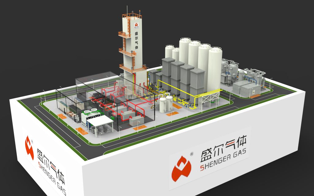
从宏观层面来看,低温空气分离包含五个步骤:(1) 压缩环境空气;(2) 去除会冻结的污染物;(3) 在主换热器中回收冷量;(4) 产生冷量形成液体;(5) 在精馏塔中蒸馏该液体。该装置的平衡点位于高压塔和低压塔之间的集成冷凝器-再沸器中,在此进行两个低温温度下的热交换,从而产生回流和沸腾。
1)空气压缩:设定压力水平并支付电费
大多数空分装置采用多级离心压缩,并在级间进行冷却,使压力接近环境温度。级间冷却可降低比功并限制排气温度,从而保护润滑剂、密封件和下游吸附剂。最终排气压力并非孤立选择,它必须满足塔压(决定饱和温度)、主换热器压降以及制冷方式(汽轮膨胀机和/或焦耳-泰勒节流)的要求。
提高排气压力可以改善冷凝温度,有时还能简化回流过程,但会增加压缩功。排气压力过低会导致冷箱和塔器结构脆弱:结垢或阀门漂移造成的任何额外压差都会消耗操作裕量,并可能表现为纯度波动或产能损失。一条实用的规则是: 低温空气分离 is to protect margin deliberately, because the cost of a narrow window is usually paid back many times in trips, off-spec product, and forced derates.
2)预净化:将冰块和干冰从冷藏箱中取出
在冷却至 0 °C 以下之前,必须去除水和二氧化碳。冰和 CO₂ 固体可能会堵塞板翅式塔道,并破坏塔的水力稳定性。在低温空气分离中,标准的安全措施是使用分子筛(通常是氧化铝加 CO₂ 选择性沸石)的预净化单元 (PPU)。吸附床在吸附和再生之间循环,产生适用于低温环境的干燥、低 CO₂ 含量气流。
对于研究人员而言,重要的动力学因素包括传质区运动、再生热波以及老化如何改变容量和动力学。对于操作人员而言,实际关注点则更为简单:稳定的出口露点和二氧化碳浓度、可重复的阀门正时以及对油分携带和颗粒过滤的严格控制。净化规范也是一个安全问题,因为某些碳氢化合物和痕量污染物如果允许向上游扩散,会在低温设备中积聚。
3)主换热器:一体化成败的关键所在。
净化后的空气进入冷箱,并在钎焊铝板翅式主换热器 (MHE) 中与返回的冷产品和废气流进行冷却。这是工厂的冷回收引擎:它通过重复利用已产生的冷量来降低制冷负荷。在现代低温空分装置 (ASU) 中,主换热器 (MHE) 通常决定着一个设计仅仅是“理论上高效”,还是真正能够跨越季节和负荷变化保持稳定。
物料交换器 (MHE) 的性能主要受两个因素影响。首先是接近温度(冷热复合材料之间的最小温差 ΔT):较小的接近温度可以减少所需的制冷量,但会增加对分布不均和扰动的敏感性。其次是压降:每损失 1 kPa 的压降都会增加压缩机的做功或降低塔压裕度。
在现场故障排除中,温度曲线的逐渐变化通常表明换热器出现结垢、分布不均或少量水分渗入。由于物料交换设备高度集成,维护期间看似微小的清洁度和干燥度问题都可能导致长期效率和可靠性下降。
4)制冷产生:涡轮膨胀加节流,策略性地应用
为了形成液态并达到低温,装置必须产生制冷。低温空气分离通常结合两种机制:
涡轮膨胀机(做功膨胀机) 气流通过涡轮膨胀,产生轴功并带来显著的温度下降。对于给定的压力比,这通常是产生冷量最有效的方式,回收的功可以被制动压缩机吸收或连接到增压器。
焦耳-汤姆逊(JT)节流。高压流体通过阀门节流至较低压力,从而产生部分液化。JT 结构简单,适用于在最适合回流或液态产品库存的位置产生液体,即使在压降较大的情况下,其效率低于涡轮机。
最佳分流方案取决于产品组成、所需液体产量(液氧/液氮)以及调幅所需的控制范围。对于必须应对负荷波动的工厂而言,为了在低温空气分离运行中获得稳定性和可控性,通常会接受较小的效率损失。
5) 蒸馏:在双塔系统中分离氧气和氮气
分离是通过精馏实现的:反复的汽液接触,其中氮气(沸点较低)富集在气相中,氧气富集在液相中。常见的工业配置是使用高压 (HP) 塔进行第一次分离,使用低压 (LP) 塔进行最终提纯。
高压塔顶的氮气在集成式冷凝器-再沸器中冷凝,形成回流。另一侧,富氧液体沸腾产生低压塔蒸汽(汽化)。该装置将塔压、热负荷和组分分布紧密耦合,这也是低温空气分离工艺表现得像一个整体系统而非独立单元操作的原因之一。
对于工程师而言,有两个运行因素至关重要。首先,压力控制的影响尤为显著:在低温条件下,饱和温度随压力快速变化,因此即使是微小的压力漂移也会导致内部温度分布发生变化,进而改变产品成分。其次,水力学因素(填料润湿性、液泛裕度和压降)在纯度指标被突破之前,就可能对稳定性产生决定性影响。

6)产品预热、交付和恢复之间的权衡
冷产品离开低压塔后,在物料交换装置 (MHE) 中被加热以回收冷量。氧气可以以气态氧 (GOX) 的形式通过产品压缩机输送,也可以以液态氧 (LOX) 的形式泵送至压力并汽化(由于泵的效率,液态氧通常适用于高压氧气)。氮气可以以低压气态氮 (GAN) 的形式输送,也可以根据需要压缩至更高的压力。
提高氧气回收率(将原料中更多的氧气转化为产品)可以提高物料利用率,但会缩小操作利润空间并增加对干扰的敏感性。因此,最佳的氧气回收目标应兼顾经济性和操作性,而不仅仅是热力学方面的考量。
典型运行目标和设计范围
以下范围代表了现代工业空分装置,最好将其视为起点;实际值取决于尺寸、方案和环境条件。
| 范围 | 典型范围 | 工程说明 |
|---|---|---|
| 爱与福出版社线 | 0.55–0.70 MPa(a) | 平衡压缩机做功与塔压和ΔP |
| PPU出口露点 | ≤ −70 °C (H₂O dp) | 冷藏箱的防冻保护 |
| CPU 后的 CO₂ | < 1 ppmv | 防止二氧化碳冻结 |
| 高压柱压力 | 0.50–0.65 MPa(a) | 设定冷凝器-再沸器温度水平 |
| 低压塔压力 | 0.12–0.20 MPa(a) | 气压降低可改善相对波动性。 |
| 典型的 GOX 纯度 | 99.5–99.7% O₂ | 通用工业规范 |
| 典型的GAN纯度 | 99.9–99.999% N₂ | 纯度越高,所需的污染控制就越严格。 |
| 比功率(参考值) | 0.35–0.60 kWh/Nm³ O₂ | 强烈依赖于方案和尺寸 |
| MHE 方法(热端) | 3–8 K | 更小的方案降低了功率,提高了灵敏度 |
| 扩展器等熵效率 | 75–88% | 影响制冷效率的关键因素 |
低温空气分离效率的最主要驱动因素是什么?
如果你想要可衡量的措施,那就关注与植物标签相对应的损失:
- 系统压降:过滤器、物料搬运设备或塔器上的压差 (ΔP) 升高会增加压缩机的做功,并降低塔器的裕量。压降审核通常能很快带来回报。
- 换热器接近温度:接近温度恶化会增加制冷负荷;曲线趋势比单点快照更有参考价值。
- 冷凝器-再沸器健康状况:导热系数降低通常会造成压力变化,通常会造成能量损失。
- 膨胀机状况:效率损失或入口质量变化会减少冷量产生,并将补偿运动推向其他地方。
- 净化稳定性:短暂的污染物波动可能会在冷箱中造成较长的可靠性拖尾,尤其是在停机或检修工作期间湿度控制出现偏差时。
结束语
低温空气分离技术仍然是工业气体供应的核心,因为它具有可扩展性,并且能够在长期运行中提供严格控制的纯度——前提是集成细节得到重视。对于研究人员而言,最有成效的工作通常集中在降低不可逆性(换热器结构、膨胀机集成)和提高可操作性(控制策略、抗干扰)方面。对于工厂工程师而言,最快的收益通常来自一些看似不起眼的领域:压降管理、净化性能和稳定的塔压控制。


