Introduction to Cryogenic Air Separation
A cryogenic air separation unit (ASU) cools atmospheric air to very low temperatures so that oxygen, nitrogen and argon liquefy and can be split by their different boiling points. In industry, these plants are chosen when large, continuous gas volumes are needed, because they deliver very high purities (oxygen typically above 99.5% and almost complete nitrogen recovery). The trade-off is power: a modern ASU usually consumes about 0.3–0.6 kWh per Nm³ of O₂ (roughly 250–500 kWh per ton) and often runs all year, producing thousands of tons of oxygen per day under tight purity control.
Cryogenic ASU plants are built in a wide range of sizes. Small skid-mounted units might produce on the order of 100–200 tons of oxygen per day, whereas very large multi-train facilities can deliver several thousand tons per day of O₂ (with proportionally larger N₂ output). In general, cryogenic air separation units become economically attractive when oxygen demand exceeds a few hundred TPD. These large installations typically operate continuously with very high reliability, but they require significant electrical power (often on the order of tens of megawatts). The high purity and multi-product capability of cryogenic ASUs make them indispensable for modern heavy industries.
Working Principles and Process Flow
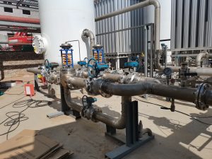
Figure: Process flow diagram of a typical cryogenic air separation unit, showing air compression, purification, distillation columns, and product recovery stages.
The cryogenic ASU process follows several key stages:
- Air Compression: Ambient air is drawn in and compressed (via multi-stage compressors) to moderate pressure (typically 5–10 bar) and cooled by intercoolers. Compressed air is required for efficient downstream cooling and distillation.
- Purification: The compressed air passes through molecular sieve beds or cold traps to remove moisture, carbon dioxide, and hydrocarbons. Any residual moisture or CO₂ would freeze in the cryogenic section, so they are stripped out at near-ambient temperature.
- Cryogenic Cooling: The purified air is fed into a main cold-box heat exchanger, where it is progressively cooled by heat exchange and expansion. Part of the air is expanded through turbo-expanders or Joule–Thomson (JT) valves to generate refrigeration, condensing most of the air into liquid form. The result is a very cold mixture of liquid and vapor near the oxygen/nitrogen boiling range.
- Distillation Columns: The cold feed enters a high-pressure distillation column, where nitrogen (bp –196 °C) preferentially vaporizes and rises, while oxygen (bp –183 °C) concentrates as liquid at the bottom. An internal condenser–reboiler links a second (low-pressure) column. In the low-pressure column, the oxygen-rich liquid boils (adding heat to the high-pressure side) and nearly pure liquid oxygen collects at the bottom. The low-pressure column also produces additional high-purity nitrogen vapor at its top. This dual-column arrangement achieves the main O₂/N₂ separation.
- Product Recovery: Oxygen is withdrawn from the bottom of the low-pressure column (usually as liquid), typically at ~99.5–99.9% purity. Nitrogen gas is drawn from the top (often 99.9%+ purity). If argon recovery is required, a side-stream of the oxygen-rich liquid is routed to a third (argon) column. Since argon’s boiling point (–186 °C) is between those of O₂ and N₂, the argon column separates ~98–99% pure argon. The residual oxygen from this column is recycled back to the main system. Finally, all product streams are warmed to ambient temperature and delivered as gas (or pumped as liquid O₂) to storage or pipeline distribution.
Common Configurations
Cryogenic air separation unit plants are built in different column configurations depending on scale and product requirements:
- Single-Column ASU: Some cryogenic air separation unit designs use a single distillation column (often with an internal reflux condenser). Single-column plants can be compact and have faster startup, but they typically have lower capacity and no dedicated argon recovery. They produce oxygen and nitrogen in one column with internal condensation and are generally suited to small on-site applications. Single-column ASUs are less energy-efficient and less flexible than larger multi-column units.
- Double-Column ASU: The most common large-scale design is a double-column cryogenic air separation unit. In this setup, one high-pressure column produces pure nitrogen vapor at its top and oxygen-rich liquid at its bottom, while a second low-pressure column produces pure liquid oxygen at its bottom and additional nitrogen at its top. A condenser–reboiler between the columns provides the necessary refrigeration. This double-column configuration delivers excellent purity and efficiency and can be scaled to very high capacities.
- Three-Column ASU (with Argon Recovery): For plants that need argon, a third column is added for argon rectification. In this arrangement, a sidestream of the oxygen-rich liquid from the low-pressure column is fed into an argon distillation column. Argon’s intermediate boiling point allows it to be separated at ~98–99% purity, with the remaining oxygen returned to the main system. Adding an argon column increases complexity, but it enables a single ASU plant to produce all three major products (O₂, N₂, Ar) on site.
Typical Capacities by Plant Size
Cryogenic ASU plants are built across a wide range of capacities. Small single-train units (often single-column) might yield roughly 50–200 tons per day (TPD) of oxygen, with about 3–5× as much nitrogen and negligible argon. Medium-scale double-column plants (hundreds to ~2000 TPD O₂) might produce on the order of 500–2000 TPD of O₂ and ~1600–6500 TPD of N₂. Large multi-column plants (over 1000 TPD O₂) can exceed 3000–5000 TPD of oxygen; such plants typically include argon recovery and can produce tens to hundreds of tons per day of argon (depending on demand). The table below gives representative output rates for example ASU scales:
| Configuration | O₂ output (ton/day) | N₂ output (ton/day) | Ar output (ton/day) |
|---|---|---|---|
| Small (single-column unit) | ~50–200 | ~150–650 | ~0–1 |
| Medium (double-column) | ~500–2000 | ~1600–6500 | ~0–5 |
| Large (with argon column) | ~1000–5000 | ~3200–16000 | ~20–150 |

Applications Across Industries
Cryogenic air separation units supply essential gases to a wide range of industries:
- Steel: The steel industry is the largest consumer of ASU-produced oxygen and nitrogen. On-site cryogenic ASUs supply pure oxygen for blast furnaces and basic oxygen furnaces, boosting combustion efficiency. Many steel plants also use nitrogen and argon for process-gas needs (e.g. inerting or cooling molten metal). Switching from air to pure oxygen in furnaces increases flame temperature and production rate while reducing fuel consumption.
- Petrochemical: Refineries and petrochemical plants rely on cryogenic ASUs to provide oxygen for processes like partial oxidation, gasification, and furnace heating. Oxygen-enriched combustion in refinery heaters improves efficiency and lowers emissions. High-purity nitrogen from the ASU is used for inerting tanks, purging reactors, and pressurizing pipelines. The ultra-dry nitrogen also meets strict purity requirements for ammonia synthesis and LNG production.
- Electronics: Semiconductor manufacturing demands ultra-high-purity gases, making ASUs critical for fabs. Cryogenic units supply 99.999%+ nitrogen for purging and 99.999%+ argon for processes like photolithography and plasma etching. By delivering these rare gases on-site at the required purity, a cryogenic ASU ensures the reliability and yield of microelectronics fabrication.
Design Considerations
Key design factors for a cryogenic air separation unit include product purity, energy consumption, and modularity:
- Product Purity: The required purity of O₂, N₂, and Ar dictates the column design and reflux ratios. Higher purity (e.g. 99.5–99.9% O₂, or 99.999% N₂ for electronics) requires more separation stages or additional columns. Each increment of purity adds energy cost and may reduce recovery. Designers optimize operating pressures, tray counts, and heat-exchanger performance to meet purity targets economically.
- Energy and Power Consumption: Cryogenic distillation is energy-intensive. Modern large ASUs achieve specific power of about 0.3–0.4 kWh per normal cubic meter of O₂ (roughly 250–300 kWh per ton O₂). Smaller or older units may need 0.5–0.6 kWh/Nm³. In practical terms, a 1000 TPD O₂ plant might draw on the order of 20–25 MW. Efficient heat integration, advanced turbo-expanders, and multi-pressure column designs help minimize power use, but energy cost remains a major factor.
- Modularity and Reliability: Many ASUs use modular construction. Skid-mounted compressors, columns, and cold boxes can be prefabricated and then assembled on-site, speeding installation. Large demands are often met with multiple parallel trains (e.g. two 1000 TPD units instead of one 2000 TPD train), providing redundancy and easing maintenance. Modular design also allows incremental expansion. Together, these approaches improve plant availability and reduce downtime.
Overall, cryogenic air separation unit design is a complex trade-off among capital cost, operating efficiency, and product specifications. Engineers must select the right column configuration, compressor size, and operating conditions to meet purity targets while minimizing power use. The result is a highly reliable plant that delivers oxygen, nitrogen and argon at the purities and scales essential for modern industry.