Cryogenic nitrogen production is a large-scale method for generating high-purity nitrogen gas by cooling and distilling atmospheric air. This process has been used for decades and is critical in industries that require ultra-high purity nitrogen. In a typical cryogenic air separation plant, ambient air is compressed, purified, and cooled until it liquefies; the resulting liquid air (a mix of oxygen, nitrogen, and argon) is then distilled by exploiting the different boiling points of its components. Because liquid nitrogen boils at –196 °C (much lower than oxygen at –183 °C and argon at –186 °C), the distillation columns separate nearly pure nitrogen vapor from liquid oxygen and argon. Cryogenic nitrogen plants routinely produce nitrogen at 99.9%–99.999% purity, far higher than most non-cryogenic methods. This ability to yield “electronic-grade” purity makes cryogenic nitrogen vital for steelmaking, chemical synthesis, semiconductor fabrication, and other applications that demand extremely clean inert gas.
Cryogenic Air Separation Process
The core of cryogenic nitrogen production is the air separation unit (ASU). Ambient air (≈78% N₂, 21% O₂) is drawn into multistage compressors and boosted to moderate pressure (typically 5–10 bar gauge) to improve refrigeration efficiency. The compressed air is then purified (moisture and CO₂ are removed by dryers and molecular sieves) to prevent ice and blockages at low temperatures. Next, the air is cooled in a series of heat exchangers (often integrated in a “cold box”) down to cryogenic temperatures. Often this cooling is aided by expansion turbines (turboexpanders) or Joule–Thomson valves: expanding a portion of the air provides the refrigeration needed to liquefy the remaining air. Typical multi-stream heat exchangers bring the air down to roughly –160 °C or lower.
In the cold section of the ASU, fractional distillation takes place. The cold, liquefied air is fed into a high-pressure distillation column (sometimes coupled with a second low-pressure column). Because nitrogen has the lowest boiling point of the major components, it vaporizes and rises to the top of the column, while oxygen (and argon) collect as liquid at the bottom. By controlling reflux flows and reboiler heat, the column produces a vapor stream of nitrogen and liquid streams of oxygen and (optionally) argon. The high purity of the nitrogen product (often ≥99.99%) is obtained because cryogenic distillation can finely separate gas species.
Figure: Simplified flowsheet of a cryogenic air separation unit (ASU). Compressed, purified air passes through a main heat exchanger and expansion turbine (at left), then flows into distillation columns where nitrogen (lighter blue) and oxygen/argon (darker blue) are separated. Liquid nitrogen (LIN) is drawn from the column and pumped or vaporized to provide nitrogen output.
The separated liquid nitrogen (LIN) is collected from the column and typically sent to insulated storage tanks. It can be stored as cryogenic liquid and vaporized on demand to supply gaseous nitrogen (GAN) at near-ambient pressure. A portion of the product nitrogen is often used as reflux within the column to improve purity. Purge (waste) gases and cold vapors are re-warmed through the heat exchangers to recover cold and may be vented to the atmosphere or used to regenerate the air purifier beds.
In summary, the cryogenic nitrogen production cycle involves three major steps: (1) Air compression and purification – ambient air is filtered, compressed, cooled, and dried; (2) Air separation and liquefaction – purified air is cooled to liquid and distilled in cryogenic columns; (3) Product handling – liquid nitrogen is stored and evaporated to supply gaseous nitrogen. These steps use large cold-box heat exchangers, turboexpanders, and high-efficiency distillation columns to achieve stable, continuous production of ultra-pure nitrogen.

Key Equipment in Cryogenic ASUs
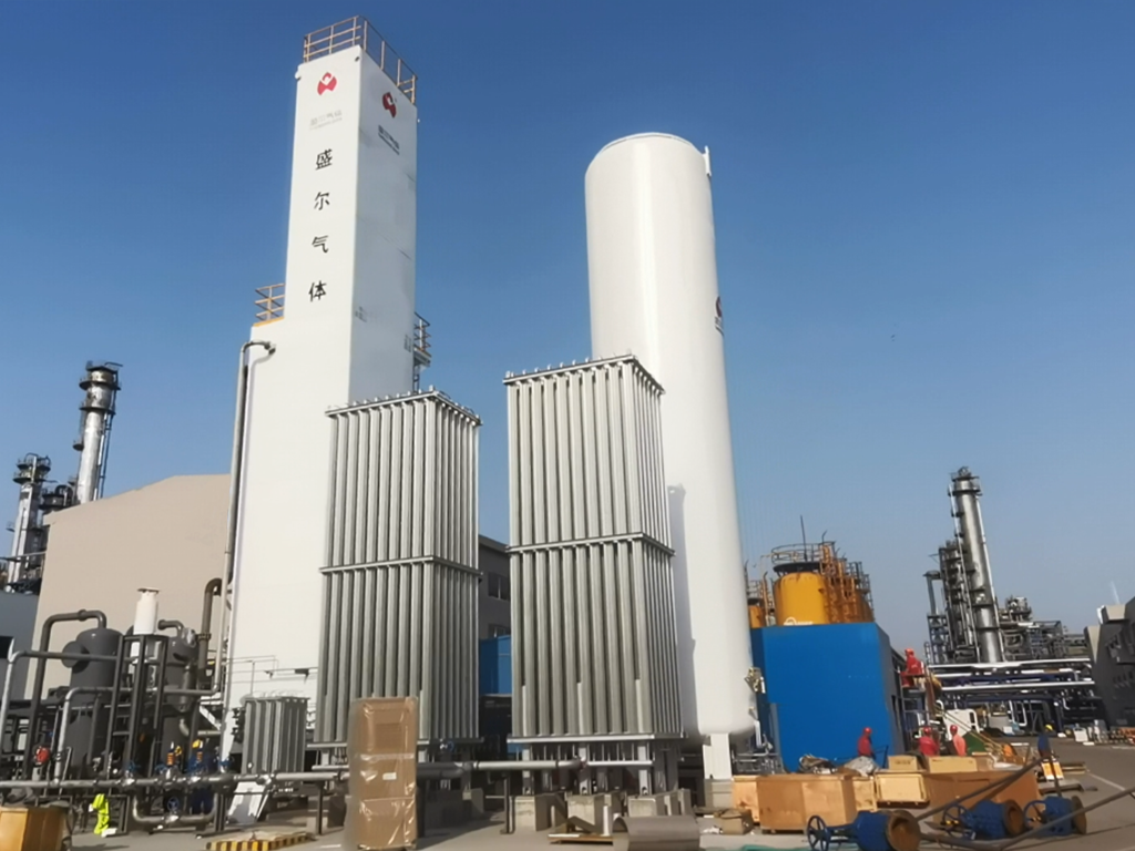
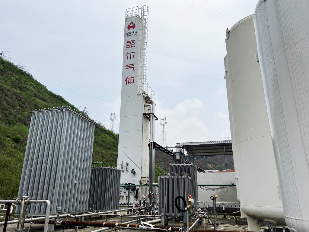
Cryogenic nitrogen plants comprise several specialized pieces of equipment. Typical ASU components include air compressors, purification skids, plate-fin heat exchangers (cold box), expansion turbines or JT valves, and distillation columns. Key items are:
- Air Compressor: Usually a multi-stage centrifugal or screw compressor (sometimes driven by gas turbines) boosts feed air to ~5–10 bar. The compressed air is then intercooled to remove heat from compression.
- Air Purification: Downstream of compression, dryers and molecular-sieve beds remove water, CO₂, and hydrocarbons. These impurities must be virtually zero to prevent freezing in the cryogenic section.
- Main Heat Exchanger (Cold Box): This multi-stream exchanger (often aluminum plate-fin or spiral-welded) cools the purified air to cryogenic temperatures by exchanging heat with returning product and waste streams. Cold nitrogen and oxygen streams from the columns are used to precool the incoming air, maximizing refrigeration efficiency.
- Expansion Turbines (Turboexpanders): Some cold is generated by expanding a portion of the high-pressure air through a turbine (as in a Linde or Claude cycle). The expanding gas drops in temperature and provides several megawatts of refrigeration for the plant. Turboexpanders (axial or radial designs) improve energy efficiency compared to simple JT valves.
- Distillation Columns: The core separation occurs in the column(s). Modern ASUs may have a high-pressure column and a low-pressure column in series. The columns contain structured packing or trays. Top and bottom (reboiler/condenser) sections manage vapor/liquid flows. For argon recovery, an auxiliary column is included to draw off a mid-column side stream.
- Product Tanks and Pumps: Liquid nitrogen is pumped to storage. The cryogenic tank (vacuum insulated) holds LIN at –196 °C. When gaseous nitrogen is needed, the LIN is vaporized in a warming exchanger and delivered under pressure.
The interplay of these components allows cryogenic plants to operate continuously and meet strict purity specifications. (For example, molecular sieve beds must regenerate using some of the cold nitrogen to keep the purifier adsorbents at low temperature.) Overall, a cryogenic ASU is capital-intensive, with large cold boxes and precision components; it typically spans hundreds of square meters and requires heavy cryogenic infrastructure.
Process Parameters and Operating Conditions
Cryogenic ASUs operate under extreme conditions. Some typical parameters are:
- Air Feed: Ambient air (≈20 °C) is compressed to about 5–10 bar gauge. Intercoolers cool the air to near ambient between stages. After final compression, the air is purified and then cooled to cryogenic temperatures.
- Temperatures: The main cold-box cools air to roughly –160 °C or lower before distillation. Within the distillation column, the top (head) temperature may be around –160 °C, while the bottom of the column approaches –190 °C or below. (Nitrogen boils at –196 °C at 1 atm, while oxygen boils at –183 °C.) Thus the column spans a range ~–160 to –190 °C.
- Pressures: The high-pressure (HP) column typically operates at its feed pressure (≈5–6 bar). If a two-column system is used, a lower-pressure (LP) column may be operated at ~1–1.5 bar to produce liquid oxygen. The LP column head pressure is near atmospheric. Product nitrogen is usually taken from the top of an LP column (or HP column if only one column is used).
- Flow Rates: Large cryogenic ASUs produce enormous nitrogen volumes (tens to thousands of normal cubic meters per hour). Production scales range from small units (a few hundred Nm³/hr) to mega-plants (many thousands). Capacity is chosen based on demand (steel mills, fertilizer complexes, etc.).
- Purity: Cryogenic units are designed for ultra-high purity. Single-train cryogenic ASUs routinely achieve ≥99.9% to 99.999% N₂. The exact purity depends on tray efficiency and reflux. Adjusting cryogenic purity is difficult in operation (it’s essentially fixed by design). In practice, most nitrogen is specified at ≥99.95% for industrial use, and higher (99.999%) for electronics.
- Ar and Other Products: When an argon side product is recovered, its purity is typically about 99.95%. The remaining waste stream (mostly nitrogen) may be used as low-purity nitrogen or vented.
The table below summarizes key parameters:
| Parameter | Typical Value | Notes |
|---|---|---|
| Feed air pressure | 5–10 bar (gauge) | Multi-stage compression |
| Main column bottom temp. | ≈ –190 °C (O₂ ≈ –183°C) | Condenser at bottom (liquid oxygen) |
| Main column top temp. | ≈ –160 °C | Head (nitrogen vapor outlet) |
| Nitrogen purity | 99.9–99.999% | Ultra-high purity (difficult to vary) |
| Argon purity (if any) | ~99.95% | Argon side column product |
| Typical flow capacity | Tens–thousands Nm³/hr | Cryogenic ASUs scale very large |
| Energy consumption | ~0.7–0.9 kWh/Nm³ | Depends on plant configuration |
Industrial Applications
Because it yields very pure, dry nitrogen in large quantities, cryogenic nitrogen production is essential for many heavy industries. The steel industry uses nitrogen as an inert and cooling gas: for example, nitrogen blanks furnaces, helps produce stainless steel by preventing oxidation, and is used for slag foaming in converters. Nitrogen is also used in pipe purging, molten metal heat treatment, and cooling of equipment (e.g. transformer and gearbox cooling in blast furnaces). Chemical and petrochemical plants require huge volumes of nitrogen for reactor blanketing, stripping, and especially for ammonia synthesis. In fact, nitrogen from a cryogenic ASU is the primary feedstock for the Haber–Bosch process, reacting with hydrogen to make ammonia (and thus fertilizers, explosives, dyes, etc.). The electronics and semiconductor industry is another major consumer: high-purity nitrogen creates inert processing environments for wafer fabrication, etching, and soldering of microcircuits.
Other significant uses of cryogenic nitrogen include food packaging (to flush oxygen from food containers), chemical analysis (to provide inert carrier gas), and even emerging fields like cryogenic cooling of superconductors. Because the cryogenic method can also supply liquid nitrogen (LIN) in tanks, it supports mobile applications like laser cutting and welding, and medical or laboratory uses. In summary, any application demanding very high purity or large flows of nitrogen (steel mills, fertilizer plants, refineries, semiconductor fabs) will often rely on cryogenic air separation units.
Cryogenic vs PSA Nitrogen Generation
Cryogenic air separation is one of several nitrogen-generation technologies. The most common alternative is pressure-swing adsorption (PSA), which uses adsorbents (zeolites or carbon molecular sieves) to separate N₂ from O₂ at near-ambient temperature. PSA generators are compact and flexible, but they have key differences from cryogenic systems:
| Feature | Cryogenic Separation | PSA (Pressure Swing Adsorption) |
|---|---|---|
| Purity | Ultra-high (99.9–99.999%) | Moderate (95–99.5% typical; up to ~99.999% in special cases) |
| Scale and Flow | Very large (tons/day) | Small to medium (hundreds of Nm³/hr) |
| Production Mode | Continuous, steady-state | Cyclic; modular towers alternate |
| Flexibility | Lower (long startup, steady output) | High (fast start/stop, load-following) |
| Energy Consumption | Higher (~0.7–0.9 kWh/Nm³) | Lower (~0.2–0.4 kWh/Nm³) |
| Capital Cost | High (complex cold boxes, large plant) | Lower (simpler adsorption towers) |
| Operating Cost | High (electricity for compressors, refrigeration) | Lower (mainly electricity to run compressors) |
| Product Form | Gas and liquid (LIN production) | Gas only |
| Argon Recovery | Yes (via side column) | No (argon remains with N₂ product) |
| Reliability | Mature for large duty | Reliable for small/medium duty |
In practice, PSA systems excel in small- to medium-scale applications due to their lower cost, simpler design, and ability to ramp up or down quickly. They can achieve high purities (often up to ~99%) and ultra-high purity (99.999%) if multiple beds and stages are used. However, PSA generators typically cannot economically reach the same purity or capacity as cryogenic plants, and they do not separate argon – residual argon will end up in the product gas if PSA is used.
By contrast, cryogenic nitrogen production is most economical at large scale. A dedicated cryogenic ASU involves significant capital outlay: cold boxes, turbines, and columns must be built and heavily insulated. The startup time is long (often 12–24 hours to cool down the system). For very large flows and when purity above 99.9% is required, cryogenic plants are preferred despite their higher investment and energy use. In fact, one industry analysis notes that a cryogenic ASU has “complex equipment, large area, high infrastructure costs, high one-time investment” compared to PSA. PSA systems require 20–50% less capital for equivalent small plants (below ~3500 Nm³/hr).
Advantages and Challenges
- Cryogenic Advantages: Very high purity (up to 99.999%) and high throughput; capability to produce liquid nitrogen; stable long-term operation; co-production of other gases (oxygen, argon) if needed. Low leakage of contaminants means product nitrogen is extremely dry and pure.
- Cryogenic Challenges: High capital and operating costs; high power consumption for refrigeration (~0.8 kWh/Nm³); complex maintenance (cryogenic equipment, insulation); slow startup and load flexibility; sensitivity to off-design loads. Purity cannot be easily altered on the fly (design is fixed).
- PSA Advantages: Lower capital cost and energy use (typ. 0.2–0.4 kWh/Nm³); compact footprint and modularity; quick start/stop and turn-down; minimal maintenance (no moving parts in adsorbers). Good for applications requiring 95–99.5% N₂ (e.g. food packaging, inerting).
- PSA Challenges: Limited capacity (not suitable for very large flows); nitrogen purity usually limited to ~99% unless multi-bed cascades are used; cannot produce liquid N₂; yields product gas contaminated with 1–5% O₂ (sometimes fine, but not for ultra-sensitive uses). PSA systems require high-purity compressed air input and use more electricity per unit N₂ than cryogenic at scale.
Overall, the choice depends on required flow rate, purity, and cost considerations. Large steel, chemical, and electronics plants typically install cryogenic ASUs, while many small laboratories or onsite systems use PSA generators. (Hybrid solutions exist too; for example, some facilities use PSA for base load and cryogenic for peak or highest-purity needs.)
Energy Efficiency Considerations
Cryogenic nitrogen production is energy-intensive due to the need for refrigeration. As noted, cryogenic plants consume on the order of 0.7–0.9 kWh per normal cubic meter of N₂ produced. This is roughly twice the energy of modern PSA systems, which typically consume 0.2–0.4 kWh/Nm³. The energy in cryogenic plants is mostly in driving the compressors and generating low-temperature heat sinks (via expanders and heat exchangers). For example, a large ASU might require motor drives of tens of megawatts.
To improve efficiency, cryogenic plants use several strategies. Multi-stream heat exchangers minimize temperature differences and recover as much cold from product streams as possible. Turboexpander cycles recover work from the expanding gas, effectively recycling energy into refrigeration. Some ASUs integrate with power plants or waste-heat sources: for instance, in an integrated gasification combined cycle (IGCC) plant, part of the gas turbine exhaust can be used to power the air compressor, effectively lowering net energy use. Advanced control of column pressures and refrigeration cycles also enhances thermodynamic efficiency.
Despite these measures, refrigeration limits the efficiency of cryogenic N₂ production. In contrast, PSA systems use no low-temperature refrigeration, so their electrical efficiency is inherently better. However, cryogenic plants often run continuously at large scale, which can be more efficient per unit volume than many small PSA units. In some cases, combined approaches are used: a PSA unit meets part of the demand and is turned off during periods of high N₂ production by the main cryogenic unit, optimizing overall energy usage.
In summary, energy efficiency is a key consideration. Designers of cryogenic ASUs must balance refrigeration load, pressure levels, and expansions to minimize power. Ongoing improvements (better expanders, advanced liquefaction processes) continue to raise the thermodynamic efficiency of cryogenic nitrogen production, but it will inherently remain more energy-intensive than non-cryogenic alternatives. The tradeoff is that for very large volumes and ultra-high purity, cryogenic separation can be the most cost-effective solution despite its energy cost.


