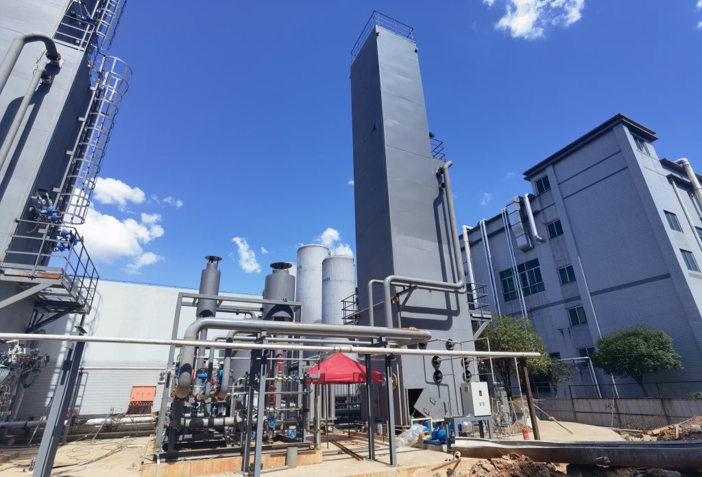
Introduction: Cryogenic air separation is the principal industrial method for large-scale production of nitrogen. In this process, ambient air is drawn in, compressed (typically to 5–10 bar), purified, and then cooled to cryogenic temperatures (around –180 to –190 °C) so that the main components liquefy and can be separated by distillation. This Cryogenic Air Separation for Nitrogen Production exploits the different boiling points of nitrogen, oxygen, and argon. Nitrogen (boiling point –196 °C) is the most volatile and is collected as an overhead vapor, while oxygen (–183 °C) condenses lower in the columns. Thanks to this fractional distillation, cryogenic units can supply very high-purity nitrogen (typically 99.5–99.99%) at high capacity. Such systems are well-suited to energy-intensive industries like LNG, where large volumes of inert gas are required.
Process Overview
The cryogenic air separation process follows these key steps:
- Air Compression: Ambient air is filtered and compressed in stages (with intercooling) to around 5–8 bar. Higher pressure increases refrigeration efficiency.
- Purification: The compressed air passes through molecular sieve adsorbers or refrigeration traps to remove water, carbon dioxide, and hydrocarbons. This prevents freezing and blockages in the cold box.
- Cooling and Liquefaction: The clean, high-pressure air is routed through multi-stream heat exchangers (cold boxes) counterflowing against cold product streams. Turbo-expanders or Joule–Thomson valves provide additional refrigeration. By about –185 °C the air is partly liquefied.
- Fractional Distillation: The cold air feed enters a high-pressure distillation column (HP column). In this column, ascending vapor carries nitrogen out of the top, while liquid oxygen (with some argon) collects at the bottom. The oxygen-rich liquid is then fed to a low-pressure column (near 1 bar), where rising vapors strip off remaining nitrogen. Pure liquid oxygen exits the bottom, and pure nitrogen vapor is drawn from the top of the LP column. Argon, if required, is typically recovered via a side column from an intermediate liquid stream.
- Product Collection: The separated streams are collected and conditioned. Nitrogen gas (∼99.5–99.99% purity) is warmed to ambient temperature and often compressed for delivery. A portion (on the order of 5–10%) is usually liquefied to liquid nitrogen (LN₂) for storage and peak demand. Liquid oxygen (LOX) is pumped or vaporized to meet its specification.
This sequence of compression, purification, cooling, and distillation efficiently yields high-purity N₂. At steady state, a well-designed ASU can continuously run with >90% uptime, using reflux and controlled temperature gradients to ensure the desired purity and recovery.
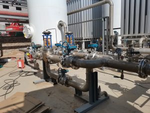
Equipment and Operation
Key equipment in a cryogenic ASU includes oil-free air compressors, purifiers (molecular sieves), plate-fin or brazed-aluminum heat exchangers (cold box), turbo-expanders, and the distillation columns. The high-pressure column typically operates around 5–8 bar, while the low-pressure column runs near 1–2 bar. The cold end of the heat exchanger (cold box outlet) is typically –180 to –190 °C, matching the boiling points of the products.
Precise control is essential: reflux ratios and column temperatures are adjusted to meet purity targets. For example, higher reflux in the LP column increases oxygen recovery (and purity), while slightly lower reflux allows more nitrogen to rise out. Thermally, the process recovers most refrigeration by counter-current heat exchange – the outgoing cold gases cool the incoming compressed air. Approximately 10% of the nitrogen is intentionally liquefied as LN₂ to store refrigeration. The remaining N₂ (>99.5%) is delivered as gas.
Below is an illustrative example of design parameters for a large cryogenic ASU serving an LNG facility:
| Parameter | Example Value |
|---|---|
| Air feed rate (standard conditions) | 67,000 Nm³/h (∼1,600 t/day) |
| High-pressure column pressure | 6 bar |
| Low-pressure column pressure | 1.2 bar |
| Cold end (cold box) temperature | –185 °C |
| Nitrogen production (gas) | 1,570 tons/day |
| Liquid nitrogen (LN₂) production | 157 tons/day |
| Nitrogen purity (gas) | ~99.5% |
| Electrical power consumption | ~30,000 kW |
Table 1: Example design parameters for a cryogenic ASU producing large volumes of nitrogen for LNG applications.
These values are representative of a modern large-scale ASU. In practice, output and power vary with design. Specific energy consumption is on the order of 0.3–0.5 kWh per normal m³ of N₂ (0.3–0.4 kWh/Nm³ is typical). (Equivalently, ~150–200 kWh per ton of O₂ produced.) High-efficiency heat exchangers and multiple expansion stages are used to reduce power draw. In some plants, part of the refrigeration is recovered by pumping liquid oxygen (which is more efficient than compressing cold gas).
Energy Use and Efficiency
Cryogenic air separation is inherently energy-intensive due to the work required for compression and refrigeration. Typical multi-stage compressors and expanders in a modern ASU consume roughly 150–250 kWh per ton of O₂ produced, or 0.3–0.4 kWh/Nm³ of N₂. The process operates continuously to maximize efficiency. Designers optimize the pressure levels: for example, an HP column at 6 bar yields more refrigeration need than 4 bar, so columns are sized and pressure chosen to balance power and equipment size. High-effectiveness heat exchangers (plate-fin) are employed to recover as much cold as possible. Turbo-expanders provide refrigeration without work input; often the energy from one expansion stage drives a booster on the opposite stream. In short, although cryogenic separation has significant power requirements, advanced engineering (optimized pressures, efficient heat transfer, and cascading expansion) minimizes the net energy per unit of N₂.
Application in the LNG Industry
In LNG facilities, large volumes of clean nitrogen are needed for multiple purposes. Cryogenic Air Separation for Nitrogen Production is therefore a key enabler of safe and efficient LNG operations. Typical LNG uses of N₂ include:
- Refrigeration: Many LNG liquefaction trains incorporate nitrogen refrigeration cycles (e.g. open-cycle Brayton loops or nitrogen expanders) as precooling or main refrigerant stages. A cryogenic ASU can supply the bulk LN₂ needed for these loops. In some train designs, excess cold nitrogen from the ASU is routed to pre-cool the natural gas feed, leveraging the cold energy of the product gas.
- Inerting and Purging: Nitrogen is used to inert storage tanks, pipelines, and process equipment to prevent flammable mixtures. For example, during LNG ship loading and unloading, tanks and hoses are purged with LN₂ to blanket against oxygen. The ASU’s liquid nitrogen inventory supports these safety operations.
- Cold Energy Integration: When LNG is regasified, it absorbs heat and yields cold energy. Advanced plants integrate this cold sink with the ASU; the low-temperature refrigerant from LNG regasification assists the ASU heat exchangers, reducing overall power. Conversely, waste cold from ASU streams can help precool LNG vapors or feed gas.
- Pipeline Nitrogen Management: If natural gas has excess nitrogen, an ASU-derived N₂ can be used in nitrogen rejection processes, although this is typically handled by dedicated NRU units. More commonly, ASU nitrogen is applied to meet specifications or feed gas turbine burners safely (e.g. in combined power cycles at LNG sites).
In practice, a large-scale LNG plant might co-locate an air separation unit on-site to meet these needs. For example, a capacity of several thousand tons per day of N₂ (with 99+% purity) may be required in a big export terminal. Cryogenic ASUs are preferred in this regime because they deliver both high purity and the liquid form (LN₂) needed for refrigeration and storage, something alternative methods (PSA or membranes) cannot easily provide at this scale.
Conclusion
Cryogenic air separation is the workhorse technology for industrial nitrogen supply. By cooling filtered air to cryogenic temperatures and using multi-stage distillation, it produces ultra-pure nitrogen efficiently and reliably. In the LNG industry specifically, such Cryogenic Air Separation for Nitrogen Production supports liquefaction by providing refrigerant and inert gas, and it can capitalize on the cold energy from regasification to improve efficiency. Modern ASUs are highly integrated systems, balancing compression, heat exchange, and expansion to meet purity and flow targets with optimized power use. For engineers designing LNG facilities, understanding the parameters and performance of cryogenic ASUs is essential: it ensures that nitrogen needs for refrigeration, safety, and process stability are met with the lowest possible energy penalty.