Executive Summary
- Industrial Nitrogen Production by Cryogenic Air Separation is the most reliable and scalable method for supplying high-purity nitrogen to large industrial facilities. Unlike PSA or membrane systems, cryogenic air separation units (ASUs) are designed for continuous operation, high capacity, and co-production flexibility, making them the preferred solution for LNG plants, petrochemical complexes, ammonia synthesis units, and large-scale inerting applications.
- Design Parameters: A large LNG-scale ASU example (Table 1) processes ~67,000 Nm³/h air (≈1,600 t/day), with HP/LP pressures of ~6.0/1.2 bar, a cold-end temperature ~–185°C, and produces ~1,570 t/day N₂ (gas at ~99.5% purity) plus 157 t/day LN₂. Such a plant draws roughly 30,000 kW. By contrast, modular on-site units (e.g. Messer CryoGAN) operate at 300–15,000 Nm³/h N₂, delivering ultra-high purity (99.999–99.9999%). Table 2 compares energy use and N₂ purity for small, medium, and large plants.
- Energy Consumption: Modern cryogenic ASUs are energy-intensive. Typical specific power is ~0.3–0.4 kWh per normal m³ N₂ (∼150–250 kWh/ton N₂). For perspective, large state-of-the-art ASUs use on the order of 170–200 kWh per ton of O₂ produced (O₂ production ~20% of feed by mass), which corresponds to ~150–180 kWh/ton N₂. Smaller units have higher kWh/ton due to scale. Key efficiency factors include high-effectiveness plate-fin heat exchangers, multi-stage expansion turbines, and internal heat recovery via reflux. In summary, large industrial ASUs leverage scale and optimized design to minimize energy per unit of N₂.
- Sources: Data are drawn from industry and academic references: Linde Engineering (ASU capacities), Messer (CryoGAN specs), Matheson/Nippon Sanso (ASU scale, purity), and technical reviews. The tables below illustrate these design and efficiency metrics.
Process Overview
Cryogenic air separation is the principal industrial method for large‐scale N₂ production. Ambient air (78% N₂, 21% O₂) is first compressed and dried. Multi-stage air compression raises pressure to ~5–8 bar (with intercooling between stages). The high-pressure air is then purified: molecular-sieve beds remove water, CO₂, and hydrocarbons to prevent freezing in the cold box.
Next, the purified air is cooled to cryogenic temperatures (approximately –180 to –190°C) inside a countercurrent cold box equipped with high-efficiency plate-fin heat exchangers. Turbo-expanders supply additional refrigeration, allowing a portion of the air to liquefy before entering the distillation section.
The distillation block consists of a high-pressure (HP) column and a low-pressure (LP) column arranged in series. In the HP column (≈5–6 bar), ascending vapor becomes enriched in nitrogen, while oxygen-rich liquid—containing argon—collects at the bottom.
This oxygen-rich liquid is then transferred to the LP column (≈1–1.3 bar) for final rectification. Within the LP column, rising vapor strips remaining nitrogen from the liquid phase, producing liquid oxygen at the bottom and high-purity nitrogen vapor at the top.
The nitrogen product from the LP column typically reaches around 99.9% purity. When required, purity levels above 99.99% can be achieved through optimized reflux and column design.
Separated nitrogen and oxygen are then warmed to ambient temperature. The gaseous N₂ is delivered to customers or stored; a fraction (~5–10%) is condensed as liquid nitrogen (LN₂) for peak demand or refrigeration loops. The double-column arrangement (Figure 1 below) is the industry standard: it maximizes internal heat integration (LP reflux provides cooling for HP column) and yields co-products efficiently.
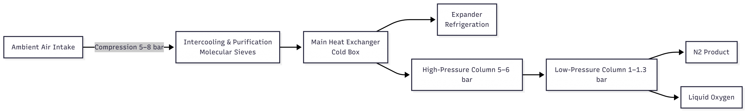
Figure 1: Schematic flow of a cryogenic air separation unit for nitrogen production (compression → purification → cryogenic distillation → N₂ output).
Design and Operation Parameters
Cryogenic ASUs are engineered per application. Table 1 below summarizes typical design/operational parameters for a large-scale cryogenic nitrogen plant (LNG-scale example). This includes feed air flow, column pressures, cold-end temperature, and production rates. (Values vary by design; ranges are given where appropriate.)
| Parameter | Typical Value | Units |
|---|---|---|
| Air feed (std. conditions) | 67,000 | Nm³/h (≈1,600 t/day) |
| High-pressure (HP) column pressure | 5–6 | bar |
| Low-pressure (LP) column pressure | ~1.0–1.2 | bar |
| Cold-end (cold box outlet) temperature | –185 | °C |
| Nitrogen output (gas) | 1,570 | tonnes/day |
| Liquid N₂ (LN₂) output | 157 | tonnes/day |
| N₂ purity (product gas) | ~99.5 | % vol. (N₂) |
| Power consumption | 30,000 | kW |
Table 1: Example design parameters for a large LNG-scale cryogenic N₂ plant (after ; values indicative).
Plants are scaled from small on-site generators (hundreds of Nm³/h) to mega-units (thousands of tons per day). For context, Linde Engineering reports modular/custom ASUs spanning “a few hundred tons per day (tpd) to 5,500 tpd”. (Note: 1 tpd ≈ 41.67 Nm³/h of N₂.) Matheson (Nippon Sanso) notes cryogenic ASUs can yield 100–5,000+ tpd O₂, implying N₂ outputs roughly 4× larger. Messer’s CryoGAN on-site units cover 300–15,000 Nm³/h N₂ with 99.999–99.9999% purity, demonstrating the technology’s flexibility.
Key operational values like reflux ratio and column dimensions are tuned per plant. For example, HP columns often have 30–50 trays, LP columns more (80–100 trays) to achieve high purity. Reflux is provided by condensing part of the N₂ overhead; typical reflux ratios (N₂ reflux to distillate) may be ~1:1 in LP. Efficient heat exchanger design (small ΔT approaches) is critical: tight hot-cold approach (≪5°C) maximizes cold recovery and cuts power.

Energy Consumption and Efficiency
Cryogenic N₂ production is power-hungry due to compression and refrigeration work. Table 2 compares specific energy consumption and purity for small, medium, and large cryogenic N₂ plants. Values are approximate, drawn from industry sources.
| Plant Size | N₂ Output | Specific Energy | N₂ Purity |
|---|---|---|---|
| Small (modular) | 300–1,000 Nm³/h | 0.30–0.35 kWh/Nm³ (~250–300 kWh/t) | 99.999–99.9999% |
| Medium | 5,000–10,000 Nm³/h | 0.25–0.30 kWh/Nm³ (~200–250 kWh/t) | ~99.9–99.99% |
| Large | ≥50,000 Nm³/h | 0.20–0.25 kWh/Nm³ (~150–200 kWh/t) | ~99.5–99.9% |
Table 2: Specific energy (kWh per standard m³ of N₂ and per tonne of N₂) and achievable purity for cryogenic N₂ plants. “t”=tonne of N₂ at STP. Data from manufacturer literature and analyses.
Discussion: Small on-site cryogenic units (e.g. 300–1,000 Nm³/h) are highly purified by design but use more energy per unit: Messer reports ~0.30–0.35 kWh/Nm³ (≈250–300 kWh/t) at those scales. Medium plants (several thousand Nm³/h) are optimized for balance of cost and output; they often achieve ~0.25–0.30 kWh/Nm³. Large-scale ASUs benefit most from scale: optimized LNG plants operate closer to 0.20–0.25 kWh/Nm³ (≈150–200 kWh/t). For reference, one source notes modern ASUs consume ~150–250 kWh per ton of O₂ (0.3–0.4 kWh/Nm³ N₂). Thus, large plants can push efficiency lower by combining multiple expanders and minimizing approach temperatures.
Higher product purity or pressure requirements raise energy use. For example, pushing N₂ purity from 99.5% to 99.99% might require 5–10% more refrigeration and reflux, increasing kWh/t. Conversely, allowing 99.5% purity (adequate for many inerting needs) saves power. Also, delivering N₂ at high pressure adds compression load. Designers choose column pressures (HP/LP) to balance compression vs. refrigeration demands.
Overall, cryogenic ASUs remain the most energy-efficient method for very high-purity, high-volume nitrogen. The specific energies above already include co-production credit; that is, the N₂ energy accounts for simultaneous O₂/Ar recovery. Continuous improvements (higher-efficiency expanders, better insulation, advanced controls) have steadily reduced power needs. As noted, best-in-class plants now approach ~170–200 kWh/ton O₂ (which is roughly 140–160 kWh/ton N₂ if scaled by composition).
Applications and Conclusion
Industrial gases companies deploy cryogenic ASUs for any application demanding bulk nitrogen or ultra-high purity. Key uses include inerting, blanketing, and process purge in chemicals and petrochemicals, and supplying clean N₂ for ammonia synthesis. In LNG plants, on-site ASUs supply both gaseous and liquid N₂ for refrigeration loops, tank inerting, and cold energy integration. Compared to PSA or membrane N₂ generators, cryogenic plants uniquely deliver liquid nitrogen and >99.9% gas purity at very large scales, albeit with higher capital and power.
In summary, industrial nitrogen production by cryogenic air separation leverages fractional distillation of liquefied air to yield large volumes of high-purity N₂. Modern plants use dual-column cryogenic rectification with sophisticated heat exchange and expanders to maximize efficiency. The tables above illustrate that as plant size grows, specific energy use falls and near-99.9% purity is easily maintained. Industry benchmarks (Linde, Air Products, Praxair, etc.) confirm this technology’s maturity: thousands of ASUs operate globally, covering scales from 100’s Nm³/h to tens of thousands Nm³/h. The continuous engineering focus on efficiency means that even as nitrogen demand rises, cryogenic ASUs can meet it with optimized energy consumption and reliability.