In many heavy and high-tech industries, oxygen and nitrogen have moved from “utilities” to “strategic resources”. Steel mills, gasification units, large chemical complexes and glass plants all depend on a stable supply of high-purity gases to run safely and efficiently. For projects with continuous demand, building or upgrading a Cryogenic Air Separation Plant is often the most economical way to secure that supply over 15–25 years of operation. A well-integrated Cryogenic Air Separation Plant also becomes part of the site’s energy and safety strategy, rather than just a stand-alone gas unit.
Unlike a short marketing brochure, process engineers care about how the Cryogenic Air Separation Plant behaves in real operation: power consumption on hot days, column stability at turndown, impurity control in the cold box, and how quickly the plant recovers after a trip. The following sections outline practical aspects of design and operation that researchers and technical staff usually focus on when evaluating cryogenic solutions.
1. Process backbone of a cryogenic air separation unit
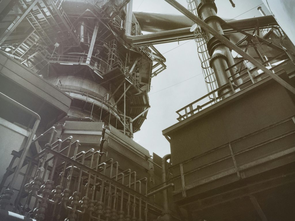
At its core, a cryogenic unit is a low-temperature rectification system wrapped around a robust compression and purification front-end. The sequence is simple on paper but demanding in execution.
1.1 Air compression and front-end purification
In any Cryogenic Air Separation Plant, ambient air is first compressed, typically to 0.5–0.7 MPa, using an integrally geared or barrel-type compressor. Intercoolers bring the discharge temperature close to ambient. Downstream, a coalescing and filtration train removes oil and particulates to protect the cold box and molecular sieves.
The molecular sieve system usually operates in a two-bed configuration. One bed adsorbs water and CO₂ while the other is regenerated with dry waste nitrogen at elevated temperature. The goal is to push residual H₂O and CO₂ down to single-digit ppm so they do not freeze in the heat exchanger or distillation columns.
1.2 Cold box and main heat exchanger
Purified air enters a brazed aluminum plate-fin heat exchanger, where it is cooled close to its dew point against cold nitrogen and oxygen streams returning from the columns. The exchanger design is one of the most delicate parts of any cryogenic unit:
- minimum temperature approach is often in the 2–4 K range,
- pressure drops must be low to avoid extra compressor power,
- distribution headers must be designed to avoid maldistribution and local hot spots.
A fraction of the high-pressure air is expanded through a turbo-expander to generate refrigeration. The expander discharge re-enters the cold box at low temperature, closing the refrigeration balance.
1.3 Double-column rectification system
The classical double-column arrangement remains standard for a Cryogenic Air Separation Plant. Air enters the high-pressure column where it splits into a nitrogen-rich overhead vapor and an oxygen-rich bottom liquid. The nitrogen overhead condenses in a condenser-reboiler that provides boiling duty for the low-pressure column.
The low-pressure column completes the separation into high-purity nitrogen at the top and oxygen-rich liquid at the bottom. When argon recovery is required, an argon side-draw from the low-pressure column feeds a crude argon column, and sometimes a pure argon column, both operating at similar pressure levels.
2. Matching plant design to industrial gas demand
No two plants look exactly the same. Even when using a standard process license, engineers adapt the configuration to local conditions and product profiles.
2.1 Product slate and purity levels
Typical industrial projects request from a Cryogenic Air Separation Plant:
- gaseous oxygen with 95–99.5 vol.% purity,
- gaseous nitrogen with residual oxygen in the 1–100 ppm range,
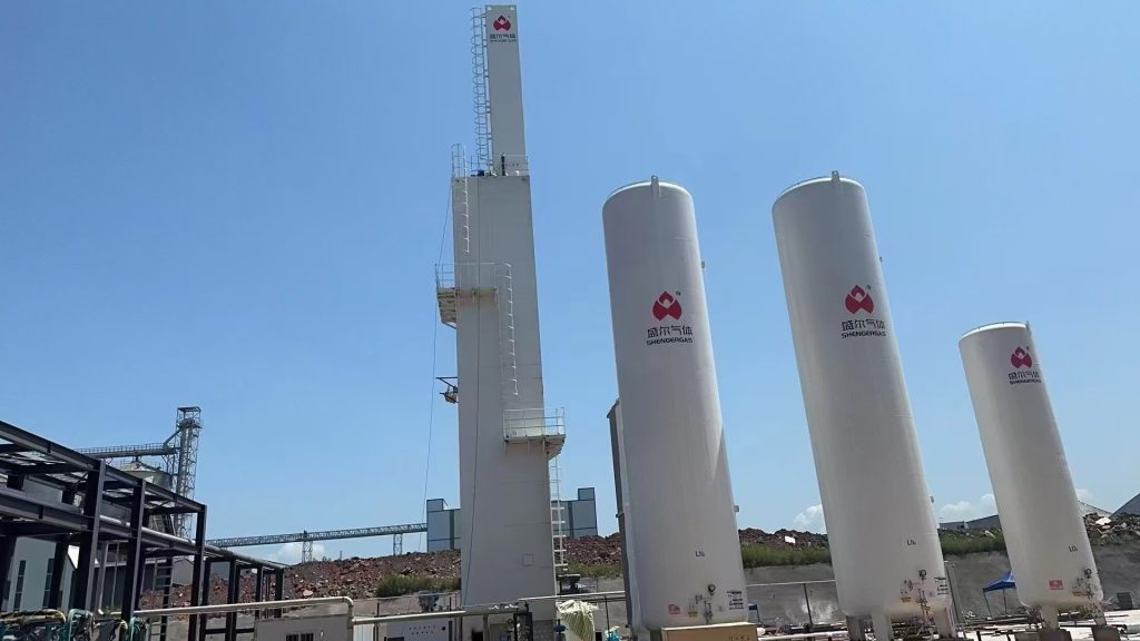
- liquid oxygen and liquid nitrogen for storage or regional sales,
- optional liquid or gaseous argon.
Higher oxygen purity usually increases power consumption and cold-box duty, so there is a trade-off between downstream process requirements and energy cost. For example, gasification units can often accept 95–97 vol.% oxygen, whereas certain chemical syntheses or medical applications may insist on 99.5 vol.% or higher.
2.2 Flow range and dynamic behavior
For a large integrated site, a Cryogenic Air Separation Plant might deliver more than 2 000 tpd of gaseous oxygen plus associated nitrogen products. At the other end of the spectrum, smaller skid-mounted units in remote locations might supply 100–150 tpd.
Important questions during basic engineering include:
- how far the plant must turndown without losing column stability,
- how quickly it must ramp up after a power dip,
- whether liquid product storage will buffer load swings or not.
These considerations influence column internals (sieve trays vs structured packing), compressor control philosophy and instrumentation density.
2.3 Site and integration constraints
Design choices are also shaped by:
- Ambient conditions – high air temperature and low winter temperatures both affect the refrigeration balance and cooling-water systems.
- Utility network – available voltage levels, cooling water quality, and whether steam or waste heat from neighboring units can be recovered.
- Plot space and layout – arrangement of the cold box, compressor house, electrical room, liquid storage and truck loading.
Well-integrated projects sometimes link the cryogenic unit to power-plant steam cycles or hydrogen production trains, turning what looks like a standalone plant into a tightly coupled part of the energy system.
3. Energy performance and power-saving options
Power cost dominates the operating budget of a Cryogenic Air Separation Plant, so even small improvements in specific energy translate into meaningful savings over its lifetime.
3.1 Typical performance ranges
The table below summarizes indicative performance data for a Cryogenic Air Separation Plant at three generic scales. Numbers vary by licensor and integration level, but the ranges reflect common industrial practice.
| Parameter | Small Unit | Medium Unit | Large Unit |
|---|---|---|---|
| Gaseous O₂ capacity (tpd) | 100–200 | 400–800 | 1500–2500 |
| Nominal O₂ purity (vol.%) | 95–99.5 | 95–99.5 | 95–99.5 |
| Gaseous N₂ capacity (tpd) | 50–150 | 250–600 | 900–1800 |
| N₂ residual O₂ (ppm) | 10–100 | 5–50 | 1–10 |
| Delivery pressure, gaseous O₂ (bar g) | 3–6 | 4–8 | 5–10 |
| Delivery pressure, gaseous N₂ (bar g) | 4–10 | 5–15 | 6–20 |
| Specific power (kWh per ton O₂) | 260–380 | 230–340 | 210–320 |
| Typical plant availability (%) | 97–99 | 98–99 | 98–99+ |
These values give engineers a simple yardstick when benchmarking tenders or evaluating an optimization study.
3.2 Design levers that influence power
Key levers include:
- Main air compressor efficiency – isothermal efficiency and mechanical design have a direct impact on specific power.
- Column pressure levels – lower column pressures reduce compressor work but can increase equipment size.
- Heat-exchanger approach temperature – tighter temperature approach improves efficiency but increases exchanger area and cost.
- Turbo-expander configuration – number of expanders, inlet pressure and flow split between expander and condenser circuits.
- Product withdrawal scheme – whether oxygen is delivered as low-pressure gas, pumped liquid, or a mix of gas and liquid.
Optimization is rarely about a single “magic” improvement. It is usually a game of small, consistent gains in many places across the process.
4. Control, automation and safe operation
Because oxygen is strongly oxidizing and cryogenic temperatures can embrittle materials, safety is built into every level of a Cryogenic Air Separation Plant.
4.1 Process control
A modern Cryogenic Air Separation Plant is typically controlled by a distributed control system. Important controlled variables include:
- pressures and differential pressures in both columns,
- liquid levels in condensers, reboilers and storage tanks,
- product purities measured by gas analyzers,
- temperature profiles across the main heat exchanger,
- compressor flow, pressure ratio and surge margin.
Start-up and shutdown sequences are normally automated, with interlocks to protect the cold box from excessive temperature gradients or upset flow conditions.
4.2 Safety and housekeeping
On the safety side, designers must avoid accumulation of hydrocarbons in oxygen-rich locations, prevent air ingress into pure oxygen lines and select materials compatible with liquid oxygen. Cleanliness is a discipline in itself: improper degreasing of oxygen lines or fittings can lead to local ignition sources.
Mechanical integrity programs, regular inspection of perlite-filled cold boxes, and careful management of vent and relief streams all contribute to long-term safe operation. Many operators now supplement classical maintenance with condition monitoring and vibration analysis of critical rotating equipment.
5. Industrial integration and application examples
Once installed, a Cryogenic Air Separation Plant becomes a backbone utility that shapes how the rest of the site is operated.
- In steel production, it supplies oxygen for blast-furnace enrichment, basic-oxygen furnace blowing and, increasingly, direct-reduced iron processes. Nitrogen from the same plant is used for purging, ladle stirring and protective atmospheres.
- In gasification and syngas production, oxygen purity, pressure and reliability directly influence gasifier efficiency and synthesis-gas quality.
- In glass and non-ferrous metallurgy, higher-purity oxygen allows hotter flames, higher pull rates and reduced fuel consumption.
- In electronics and specialty chemicals, high-purity nitrogen with well-controlled trace impurities is often more valuable than the oxygen stream.
In many of these applications, the cryogenic unit does more than just “make gas”. It interacts with power-purchase agreements, steam cycles, emergency power strategies and even regional liquid-product logistics.
6. Closing remarks
From a research and engineering perspective, a Cryogenic Air Separation Plant is an excellent example of how classical thermodynamics, advanced machinery and modern control come together in real industrial practice. For project teams, the challenge is less about inventing a new separation principle and more about making a robust, energy-efficient and maintainable plant that fits the local grid, climate and production strategy.
When evaluating different designs or vendors, it is useful to look beyond headline capacity and purity numbers. Attention to specific power, part-load performance, start-up behavior, safety philosophy and life-cycle maintenance will often make the difference between a plant that merely runs and a plant that quietly supports the site for decades with minimal drama.


