Cryogenic air separation has long been the workhorse for producing industrial gases at large scale. It is a process that cools air to extremely low temperatures until it liquefies, then distills it to separate oxygen, nitrogen, argon, and other gases(For physical property data, see NIST Chemistry WebBook:https://webbook.nist.gov. This technology underpins many industries – from traditional steel mills relying on vast oxygen supplies, to emerging hydrogen hubs requiring nitrogen and oxygen for clean fuel production. In recent years, next‑generation cryogenic air separation systems have begun to transform this mature technology, bringing improvements in efficiency, flexibility, and integration that align with new industrial demands.
In this article, we explore how cryogenic air separation works and its pivotal role in heavy industries. We then examine advancements in the technology that make modern air separation units (ASUs) more efficient and adaptable. Finally, we discuss the expanding role of cryogenic air separation in the hydrogen economy – the so-called hydrogen hubs – which represent a new frontier for this century-old separation process. The journey of cryogenic air separation from steel mills to hydrogen hubs illustrates both continuity in industrial gas supply and innovation in the face of evolving energy needs.
Cryogenic Air Separation: Process Overview and Significance
Cryogenic air separation is the primary method for producing high-purity oxygen, nitrogen, and argon in large quantities. The process operates on the principle of fractional distillation at cryogenic temperatures. Air is first filtered, compressed, and cooled, then fed into a distillation system where it is separated into its components by boiling point(For industrial gas safety standards, refer to EIGA: https://www.eiga.eu). Oxygen (boiling point ~–183°C) liquefies and separates at a different stage than nitrogen (boiling point ~–196°C) and argon (–186°C), allowing each gas to be drawn off in purified form. The entire system is housed in insulated “cold box” towers that loom over industrial sites – a familiar sight at steel plants, refineries, and chemical complexes.
Cryogenic air separation can achieve very high purities (oxygen and nitrogen >99.5%, argon >99.9%) which are often required for critical applications. It also scales exceptionally well. For example, a single large ASU can produce thousands of tons per day of oxygen or nitrogen(Energy benchmarks for large ASUs available at DOE AMO: https://energy.gov/eere/amo). This makes it the technology of choice for “tonnage” industrial gas production where no other method (like adsorption or membranes) can economically reach the required volume and purity. The drawback is energy intensity: compressing and cooling air to cryogenic temperatures consumes significant power. A typical ASU producing ~1,000 tons of O₂ per day might draw tens of megawatts of electricity – comparable to the power usage of a small town. Thus, while cryogenic plants provide indispensable capabilities, they also come with challenges of efficiency and operating cost.
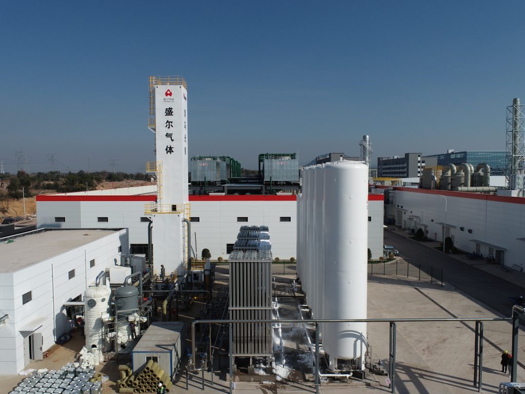
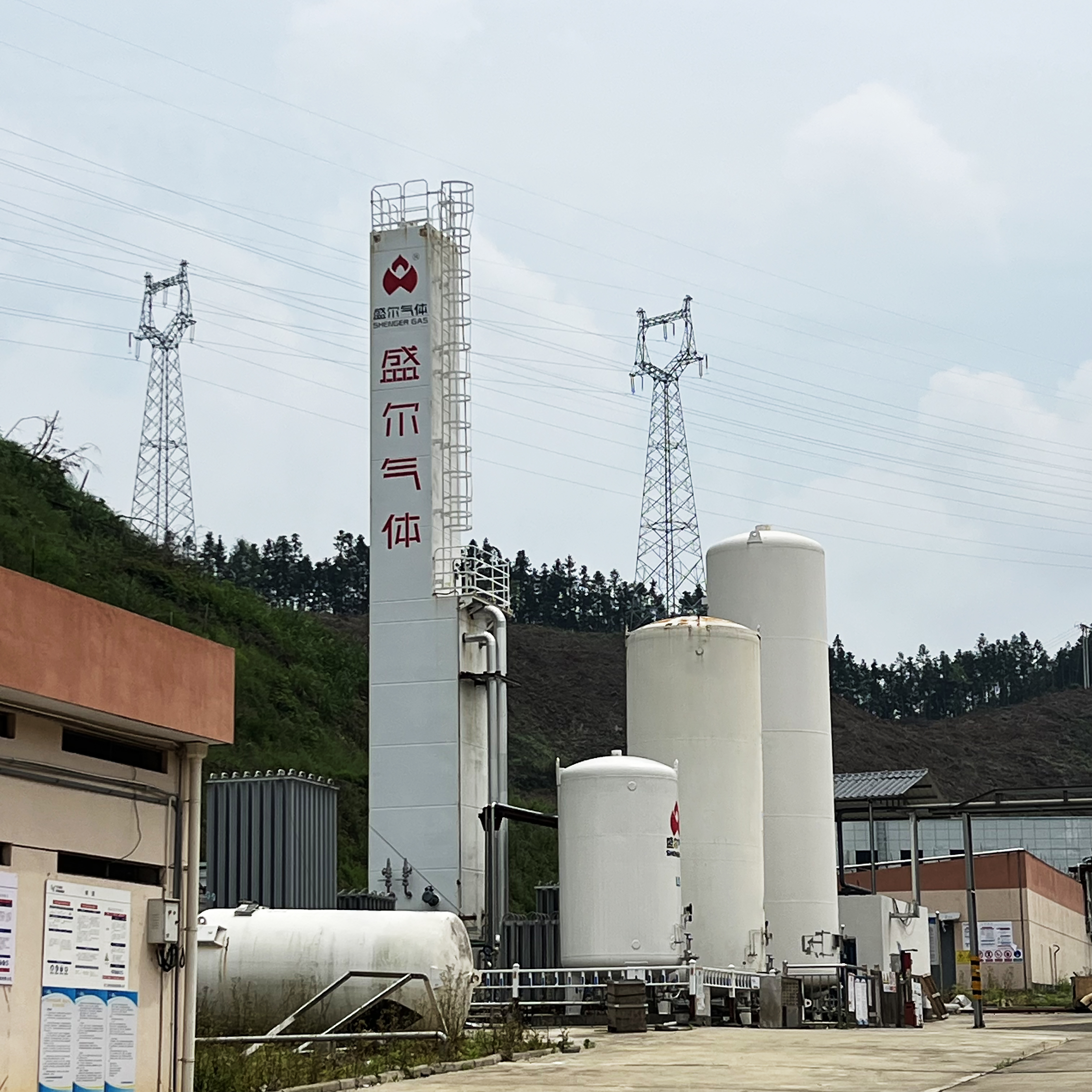
A cryogenic air separation unit cold box assembly for oxygen production. Cryogenic ASUs like this have been the backbone of industrial gas supply for decades, and new innovations are now improving their efficiency and flexibility.
From an industrial perspective, cryogenic air separation is foundational. It supplies oxygen for processes such as steelmaking, glass manufacturing, and gasification; nitrogen for inert atmospheres, chemical blanketing, and fertilizer production; and argon for welding and electronics manufacturing. These gases are so essential that many large facilities install on-site ASUs to ensure a reliable, continuous supply. Historically, steel mills were among the first to adopt on-site cryogenic air separation on a massive scale – setting the stage for today’s even larger and smarter ASUs that are now expanding into hydrogen production sites.
Steel Mills: Traditional Domain of Cryogenic Air Separation
The steel industry has a long and enduring relationship with cryogenic air separation. In integrated steel mills, the basic oxygen furnace (BOF) process consumes a tremendous volume of oxygen to convert iron into steel. On the order of 100 Nm<sup>3</sup> of O₂ is blown per ton of steel produced. This means a large steel plant can require thousands of tons of oxygen per day. Cryogenic ASUs located adjacent to steel mills (often owned or operated by industrial gas companies) supply this oxygen continuously via pipelines. In addition, they provide high-purity nitrogen for furnace sealing and safety inerting, and argon for refining the steel (argon stirring in ladles to remove impurities).
Over decades, ASUs serving steelworks have grown in scale to meet rising production. It is not uncommon for a single modern oxygen plant at a mill to produce 2,000–3,000 tons per day of gaseous oxygen, plus additional liquid reserves. Some of the world’s largest ASUs – with oxygen capacities above 4,000 TPD – have been built to support metallurgical and energy complexes. These huge plants leverage economies of scale, efficiently producing oxygen alongside co-products nitrogen and argon. In steel mills, the reliability of supply is paramount: the ASU must run 24/7 to keep up with continuous furnace operations. Traditional ASUs are designed for steady output and high on-stream factors (often >95% uptime), which aligns well with the around-the-clock nature of integrated steel production.
Energy efficiency and cost have always been concerns, since producing oxygen in such volumes consumes massive power. For context, an oxygen plant feeding a steel mill can draw 50 MW or more of electricity, incurring substantial operating cost. Over the years, incremental improvements have been made – better compressors and expanders, improved heat exchanger design, and optimized process cycles – to shave down the kilowatt-hours required per ton of oxygen. For example, advanced turboexpanders with higher isentropic efficiency and lower loss can help reduce the energy per unit of product. Also, internal process optimizations (like pumped liquid oxygen delivery and heat integration) have improved efficiency in many modern ASUs. These gains are vital for steel companies, where oxygen cost factors into overall steelmaking economics.
Beyond oxygen, steel mill ASUs also monetize byproducts. Argon, in particular, is a valuable rare gas that cryogenic units can extract from the small 0.9% fraction in air. High-capacity steel plant ASUs typically include an argon separation column to produce liquid argon, which is then sold for use in welding, lighting, and electronics. This adds complexity but improves the profitability and resource efficiency of the air separation process. Nitrogen produced in excess of steel mill needs can also be liquefied and sold for other applications (food freezing, etc.). In this way, the cryogenic ASU at a steel site often serves both the captive needs of the mill and the wider industrial gas market.
In summary, steel mills established the template for cryogenic air separation at scale: large, energy-intensive plants delivering continuous oxygen and nitrogen flows. This traditional domain honed the technology and pushed it toward better performance. Now, the lessons and capabilities from steel applications are informing a new generation of ASUs built for the demands of the clean energy transition.

Next-Generation Cryogenic Air Separation Technologies
Meeting today’s industrial challenges has driven innovation in ASU design and operation. Next-generation cryogenic air separation technologies focus on higher efficiency, greater flexibility, and improved integration with other processes. Engineers and industrial gas companies are rethinking many aspects of the classic ASU to make it smarter and more adaptable for modern needs.
One key area of advancement is energy efficiency. Although cryogenic distillation is already the most efficient method for bulk separation of air, there remains a significant gap between theoretical minimum energy and actual consumption. New ASU designs target this gap through several approaches:
- Improved machinery – State-of-the-art centrifugal compressors and expanders with better aerodynamics and lower friction losses can reduce the specific power (kWh per unit of gas produced). For instance, using high-efficiency expansion turbines can recover more energy during the cooling cycle, directly cutting power requirements or enabling more liquid production without extra energy.
- Advanced materials and heat exchangers – Novel heat exchanger designs (such as brazed aluminum plate-fin exchangers with optimized fin structures) enhance heat transfer, allowing closer approach temperatures and less wasted cold energy. There is also research into additive manufacturing (3D printing) of micro-structured distillation columns, which could increase separation efficiency by improving contact between vapor and liquid in the column.
- Process cycle innovation – Next-gen ASUs sometimes adopt different process configurations. One notable concept is the single-column ASU design (pioneered by Praxair/Linde for certain use cases) which can produce high-purity oxygen in one column instead of the traditional double-column arrangement. By eliminating the need for a separate lower-pressure column for nitrogen, this design simplifies the process and can improve efficiency and capital cost for applications that only require oxygen (~95% O₂ purity) without co-production of argon. Such streamlined cycles are possible when ultra-high purity or full product slate is not needed.
Another major focus is operational flexibility. Classic cryogenic plants run best at steady state and have limited ability to adjust output quickly – typically they can only turn down to around 60–70% of capacity before risking process instability (the distillation columns rely on a certain throughput and liquid inventory to function). However, the evolving energy landscape now rewards industrial systems that can dynamically follow power availability and demand fluctuations. To enable this, next-gen ASUs incorporate features for fast ramping and turndown:
- Liquid storage and backup – Modern ASU facilities often include large cryogenic storage tanks for liquid oxygen, nitrogen, and argon. These tanks act as buffers that decouple production from instantaneous demand. For example, when electricity is cheap or surplus (e.g. during a windy night), an ASU can produce extra liquid products and store them. Later, when power is expensive or if the grid is strained, the ASU can throttle down its air compressors and instead draw on the stored liquid to supply customers. This effectively allows the plant to “coast” for some hours with minimal power use while still meeting gas demand. Increased storage capacity is a relatively straightforward but powerful tool for flexibility.
- Rapid power modulation systems – Engineers have added clever process sidestreams to ramp production down or up quickly. One technique is using an auxiliary refrigeration loop that can take over cooling duty, or pumping liquid back into the columns to maintain low temperature while reducing air feed. In practice, an additional liquid pump can be installed to recirculate product from the storage tanks into the distillation column. Doing so keeps the column cold and maintains product purity with much lower energy input. Some advanced ASUs can achieve an 80% reduction in power consumption within minutes by employing this method, essentially idling the plant without a warm shutdown. When the time comes to resume full production, the system can ramp up faster since the cold condition is preserved.
- Robust design for cycling – Next-gen air separation units are being built with more resilient components to handle frequent load changes. This includes thicker-walled pipes to accommodate pressure fluctuations, control valves and instrumentation tuned for a wider operating envelope, and compressors that can tolerate more starts/stops or variable speeds. Whereas older ASUs were not expected to shut down except for maintenance, the new philosophy is to design ASUs that can load-follow daily or even hourly changes. Linde’s FLEXASU® concept, for example, explicitly aims to create an ASU that can modulate production on demand to assist grid balancing, effectively operating in tandem with renewable energy availability. This is a radical departure from the past, essentially transforming the once steady “gentle giant” oxygen plant into a flexible asset more akin to a peaking power plant in its responsiveness.
Next-generation systems also embrace digital controls and automation to manage complexity. Smart control systems, predictive analytics, and AI-based optimizations are increasingly being used to fine-tune ASU operations. These digital tools can predict demand swings or energy price spikes and adjust the plant proactively. They also help maintain stability during transitions, ensuring product purity doesn’t suffer when ramping quickly. The result is a more intelligent ASU that can autonomously balance efficiency, reliability, and flexibility according to real-time conditions.
Finally, we see new applications and integrations that extend the capabilities of cryogenic air separation. One exciting area is integrating ASUs with processes that use or generate the separated gases in novel ways. For example, there are projects coupling ASUs directly with gasification or oxy-combustion power generation systems, where the high-purity oxygen stream is fed into a power plant that burns fuel in oxygen instead of air to enable carbon capture. In such cases, waste heat from the power plant can be utilized by the ASU for regeneration or boil-off, improving overall efficiency of the combo. Another integration concept is pairing ASUs with liquid air energy storage (LAES) systems – using off-peak power to liquefy air for energy storage, then expanding it to generate electricity when needed. The cold energy from rewarming liquid air can potentially be recycled into the ASU’s refrigeration cycle, forming an innovative symbiosis between energy storage and industrial gas production.
Through these advances, next‑gen cryogenic air separation is far more versatile and efficient than its predecessors. These improvements are timely, because a new wave of demand is on the horizon – driven by the global shift toward a hydrogen economy.
Hydrogen Hubs: A New Frontier for Cryogenic Air Separation
Hydrogen hubs are emerging industrial clusters focused on the production, utilization, and distribution of hydrogen as a clean energy carrier. Whether the hydrogen is “green” (from renewable-powered electrolysis) or “blue” (from natural gas with carbon capture), these hubs often involve large-scale hydrogen generation and conversion to derivatives like ammonia(For global hydrogen hub insights, see IEA Global Hydrogen Review: https://www.iea.org/reports/global-hydrogen-review-2024). At first glance, separating air might seem tangential to making hydrogen. In reality, cryogenic air separation is a crucial enabling technology in many hydrogen hub configurations – providing both oxygen and nitrogen that facilitate hydrogen production, processing, and transport.
One important role is supplying oxygen for hydrogen production processes. In conventional “blue hydrogen” facilities, hydrogen is produced via steam methane reforming (SMR) or autothermal reforming (ATR) of natural gas. While SMR uses steam, ATR and gasification-based routes require a pure oxygen feed to drive the reforming reaction or gasifier. Historically, large ASUs have been coupled with gasification plants (for example, in coal-to-liquids or refineries) to deliver oxygen. The new hydrogen hubs employing ATR for low-carbon hydrogen similarly depend on on-site cryogenic ASUs to furnish high-purity oxygen(Example of large-scale integration: Air Products NEOM project – https://www.airproducts.com/neom). These oxygen-hydrogen plants can be massive; for instance, an ATR-based hydrogen plant producing millions of cubic meters of H₂ per day may need on the order of 1,000–2,000 tons of O₂ per day to feed its reactors. Only cryogenic air separation can supply such oxygen volumes economically. The oxygen is consumed in converting methane into syngas (CO + H₂), which is then shifted to hydrogen and CO₂ (the CO₂ is captured, hence “blue”). Without an ASU, the required oxygen would be impossible to obtain at needed scale and purity.
Another critical contribution of cryogenic air separation in hydrogen hubs is nitrogen supply. When producing green hydrogen via electrolysis, hydrogen gas is often not the final product for transport – instead, many projects plan to convert hydrogen into ammonia (NH₃), which is easier to ship and store. Ammonia synthesis (by the Haber-Bosch process) requires a continuous source of high-purity nitrogen to combine with hydrogen. This is where air separation comes in: an ASU can generate the large nitrogen stream needed to make ammonia. A flagship example is the NEOM project in Saudi Arabia – a green hydrogen/ammonia plant that includes a gigantic air separation unit dedicated to producing nitrogen, which is then reacted with hydrogen from electrolyzers to yield 1.2 million tons per year of green ammonia. In such facilities, the ASU effectively operates as a nitrogen generator. It takes in air and outputs nitrogen (at purities often 99.9% or higher) while the by-product oxygen from the air is typically not needed (electrolyzers themselves produce oxygen as a by-product of water splitting). The ability of cryogenic units to produce nitrogen at scale with low residual oxygen (essential for ammonia synthesis catalysts) makes them indispensable for green ammonia and fertilizer plants tied to hydrogen hubs.
Beyond ammonia, nitrogen also plays a safety and support role in hydrogen systems. For instance, large electrolyzer installations may need nitrogen for purging and blanketing. During dynamic operations or shutdowns, inert nitrogen is used to purge oxygen out of equipment and prevent explosive H₂/O₂ mixtures. Instead of trucking in liquid nitrogen, hydrogen hubs will likely incorporate on-site nitrogen production. Next-gen cryogenic ASUs can be tailored for this purpose: nitrogen-only plants (sometimes called stand-alone nitrogen generators) focus solely on N₂ output without producing oxygen or argon co-products. By not handling the oxygen product, these units simplify the plant design and reduce power consumption per unit of nitrogen. They essentially are a scaled-down, optimized version of an ASU where the process is adjusted to vent or minimalize the oxygen. This approach is attractive when a hydrogen hub only needs large amounts of nitrogen (for ammonia or purging) and has little use for the oxygen fraction.
The different needs of steel mills versus hydrogen hubs for air gases highlight how cryogenic air separation technology is adapting to serve both. The table below summarizes some key differences in requirements and design emphasis:
Table: Comparing Traditional Steel Mill ASUs and Hydrogen Hub ASUs
| Aspect | Steel Mill ASU (Traditional) | Hydrogen Hub ASU (Next-Gen) |
|---|---|---|
| Primary Purpose | Supply continuous O₂ for blast furnaces/BOFs (steelmaking). Co-produce N₂ and Ar for metallurgical uses and sales. | Supply O₂ for processes like ATR gasification (blue H₂) or N₂ for ammonia synthesis and inerting (green H₂ hubs). Often focused on a specific product (O₂ or N₂) as needed. |
| Typical Scale | Very large, e.g. 2,000–3,000 TPD O₂ (single train) serving constant demand. | Large as well (on the order of thousands of TPD gas). For example, ~2,700+ TPD N₂ for a green ammonia plant, or similar O₂ tonnage for a gasifier. Can also be modular if phased with project growth. |
| Product Purity | O₂ ~95–99.5% purity for steelmaking; N₂ and Ar typically high purity (99.9%+). Argon recovery included. | O₂ ~99+% for oxygen-fed hydrogen production (if needed); N₂ often 99.9% for ammonia. Argon may not be recovered if focus is on a single product (simpler plant design). |
| Operation Mode | Continuous steady operation 24/7. Load swings are minimal; designed to run at constant rate for reliability. | Often designed for dynamic operation. If tied to renewable power or varying hydrogen demand, may ramp up/down daily. Incorporates liquid storage to buffer output and handle intermittent operation. |
| Efficiency Focus | Optimize energy per ton of O₂ for base-load operation (important due to high power cost over long periods). Incremental efficiency improvements (better compressors, etc.) deployed. | Optimize both energy efficiency and flexibility. Able to run efficiently at partial loads. Designs include features to maintain good efficiency even when cycling or in standby modes. |
| Integration | Stand-alone on steel site; occasionally heat integration from steel plant is minimal (some low-level heat recovery or sharing of utilities). Mostly an independent utility unit. | Often highly integrated into hydrogen hub infrastructure. For blue H₂, ASU is interlinked with reformer/gasifier (O₂ supply and potentially sharing of cooling water, etc.). For green H₂, ASU (for N₂) is coordinated with electrolyzers and ammonia plant; may operate in concert with renewable energy availability. |
| Flexibility Upgrades | Traditional ASUs have limited turndown (≈60–70%). Recent upgrades at some steel plants include adding backup liquefiers to handle excess production or provide some buffer, but not originally built for daily cycling. | Next-gen ASUs are built with flexibility as a core feature – e.g. thicker pipes, advanced control systems, extra pumps and large tanks for rapid turndown and ramp-up. They can participate in demand response, adjusting to grid conditions or hydrogen production schedules without compromising gas supply. |
As shown above, the next generation of cryogenic air separation in hydrogen hubs extends the capabilities beyond the steady, continuous service traditionally seen in steel manufacturing. In hydrogen applications, an ASU might switch between acting as an oxygen plant and essentially idling, or as a nitrogen producer that can vary output as needed. This adaptability is crucial because many hydrogen hubs are tied to renewable energy, which is inherently variable. If a hydrogen hub is powered by solar and wind, the ASU supplying it must also handle variable power input. We now see ASUs that can ramp production up when excess renewable electricity is available (making extra hydrogen or ammonia possible), and then ramp down to conserve power when the sun sets or the wind calms. The ability to “air-separate on demand” ensures that the upstream hydrogen production isn’t bottlenecked by gas supply constraints.
It’s also worth noting that advanced cryogenic systems remain complementary to other gas separation technologies in these hubs. For instance, pressure swing adsorption (PSA) units might be used for smaller nitrogen needs or polishing of hydrogen, but for bulk production of N₂ or O₂ at high purity, cryogenic methods maintain a clear advantage. In some cutting-edge hydrogen projects, designers consider hybrid approaches – using PSA or membrane units for a portion of production and a cryogenic ASU for the rest, to balance capital cost and purity requirements. Nonetheless, the cryogenic ASU often ends up as the central utility in any large-scale hydrogen complex, due to its versatility and scale.
Conclusion
From the fiery furnaces of steel mills to the clean energy ambitions of hydrogen hubs, cryogenic air separation continues to be a linchpin technology. Its core principle – distilling air into pure oxygen, nitrogen, and argon – remains unchanged, but the implementation is evolving rapidly to meet new demands. In steel manufacturing, these plants delivered the huge oxygen volumes that enabled modern high-tonnage steelmaking, establishing benchmarks for reliability and efficiency. Today, as industries pivot towards decarbonization, next‑gen cryogenic air separation is stepping up to support emerging needs: providing oxygen and nitrogen for low-carbon hydrogen production, ammonia-based energy storage, and more flexible operation in tandem with renewable power.
The next‑gen ASU is not your grandfather’s oxygen plant. It is smarter, more efficient, and more responsive – capable of producing ultrahigh purity gases at lower energy cost, and of flexing its output to balance an increasingly renewable grid. Innovations like flexible operation modes, modular designs, and integration with hydrogen processes ensure that cryogenic air separation will play a key role in the new hydrogen economy. At the same time, continued improvements in energy efficiency help reduce the carbon footprint and operating cost of these units, addressing concerns about their intensive power usage.
In essence, cryogenic air separation is a mature technology reinventing itself for a new era. Its journey from traditional steel mills to cutting-edge hydrogen hubs exemplifies the adaptability of industrial technologies in response to global shifts. Engineers and researchers will no doubt keep pushing the boundaries of what air separation units can do – whether that’s achieving even higher efficiency, enabling completely load-flexible “air separation on tap,” or pairing with novel processes in ways we have yet to imagine. With these advancements, cryogenic air separation remains a foundational pillar of modern industry and a critical enabler of both current production and future energy systems. As we move toward a cleaner and more hydrogen-fueled world, this venerable technology is proving that it can reinvent itself and continue to deliver the gases that industries need, wherever the future leads.


